I was inspired by the slightly misguided noPhoto product (I don't want to be the guy who blinds the drivers behind me with a flash. Flashing lights are illegal on moving vehicles, if you get caught.)
http://laughingsquid.com/nophoto-license-plate-frame-that-thwarts-traffic-cameras/
to design a speed camera blocking device that would be safe, mostly legal and effective. When I say legal, I mean only that it passes the common sense test and the spirit of the laws commonly in place. You can't cover the plate. You can't alter the plate. You can't obscure the plate. You can't put bright lights, flares or strobes on your car. Your jurisdiction may vary, and laws constantly change, so I promise nothing. Legal is your problem. This blog is for fun only.
Flashback seems like a great idea at first, and this guy ran with it. Others have posted this idea and even tried it before. Basically standard photography equipment flash repeater equipment is all you need. A photo sensor picks up the flash and fires another flash. Flash photos generally work by opening the shutter for quite a bit longer than the duration of the flash to allow for the timing uncertainties. Flash repeaters work by firing another flash while the shutter is still open.
I had originally abandoned this idea only because I felt speed cameras, in daylight, taking pictures of moving vehicles, would have a pretty fast shutter. I also thought that the camera flash would be hard to detect. Some readers of my blog tried it, and showed that it can actually work. I guess photographers solved this problem long ago, and given a high dynamic range camera and a powerful flash, OK, it might work. I didn't do the math.
One minor hole in his video is that his prototype is NOT MOVING. So his SLR camera can have any shutter speed he wants, and the flash can have any profile he wants. When he shows this working on a moving vehicle you might believe it.
My current design, discussed in these pages is simply a constant on IR LED array that seeks to flood the CCD camera with charge and ruin the picture, or cause the auto exposure control to mistakenly set the exposure too short, by directly pointing high intensity bulbs at the camera. I wrote several posts on it's design and evolution:
http://blog.workingsi.com/2011/06/improved-high-power-ir-led-speedred.html
http://blog.workingsi.com/2011/05/ir-led-speedred-light-photo-blocker.html
However it is only effective in a narrow range of lighting conditions. Many readers have suggested a flashback system like the noPhoto, and that really is the best way to ruin the still frame shots. But you can't use a visible flash, so I'll use an invisible IR flash. You want to be able to detect IR speed camera flashes as well. That will take some experimentation.
The diodes I used get wicked hot in the configuration where they are constantly on. Think about your LED light bulbs from Home Depot. Plus they can't hit their max power because they overheat. You can get considerably more intensity out of them if they are just pulsed once when needed.
Also, I'm willing to change my opinion and experiment with illuminating the plate rather than shining the light straight at the camera and see what works best. I'll take flash pictures and judge them. I liked the noPhoto clear plastic light conduits on each side, I may use a similar technique for piping light to the edges of the plate.
This time I'm going to start with some commercial hardware, throw the works at it, and then pare down to a custom device later after I prove the prototype. My reason is, it is faster and more likely to succeed re purposing commercial hardware and shooting high.
The first key piece is an IR flash. These are for hunters to capture nighttime photos of game...A little pricey but less than the price of a single ticket. They all have about 100 LEDs. I made need to modify them to boost power, but they are
already for outdoor use. Weatherproofing was a major pain for my homebrew solution.
I'm not sure if any of these include a flash trigger, or if I'll have to get one separately or build one.
A little googling found the manufacturers site and instructions.
www.hcodealer.com/product_info.php?products_id=47
http://www.hcodealer.com/download/Users_manual_Uway_XtendIR-B.pdf
Uway Flash Extender XtendIR-B (Blackout IR Flash)
110 High Output LED Array
Main Enhancement LED Bank (60 Leds)
Wide Angle Illumination Bank (20 Leds)
Distance Illumination Bank (30 Leds)
Adjustable illumination from 40 to 60+ feet (standalone)
3 foot Infrared Sensor Cable connects to ALL IR cameras
Functions in Photo and Movie Modes
Uses 4 "D" Cell Batteries Internal(Ni-MH rechargeable batteries are recommended)
6 Volt External Battery port
Innovative Curved rear mounts provide both mounting and security using strap, bungee and python lock
Adjust angles up and down for easy camera alignment
Brown Anti-Reflective Color Surface
Patent Pending
Extend flash range of all blackout invisible flash cameras and convert ALL IR cameras to blackout invisible flash. You may find more information about this product and test results at Chasingame.Please click here for Uway Flash Extender XtendIR-B User's Manual.
It looks like it has a flash sensor, but it is really really low sensitivity. I'll have to shop for something better or build something. Meanwhile I'll order the flash for testing.
This is an example of a slave flash trigger. I'm not going to get this one yet, because I don't know if it would require modification. Looks like a lot of photography equipment has gone to wireless master/slave flash setups using RF. I need the old fashioned optical type. This one probably doesn't have the performance I need.
Some more googling on photography web sites for information on optical slave triggers. Seems they are triggered by both IR and visible. So I'll have to take back my comments on the noPhoto. But photographers do say that sun interferes with them and they only really work well in the studio.
http://www.diyphotography.net/using-infra-red-masters-to-trigger-optical-slaves
http://www.scantips.com/lights/slaves.html
This website sells project boards for a flash slave unit. Cool.
http://www.pixcontroller.com/SlaveFlash/Flash_Units.htm
http://www.pixcontroller.com/SlaveFlash/Flash_About.htm
Photo sensing is not hard, but we are going to need pretty high performance sensor. A few false triggers is OK, since the power supply is the car battery and is endless.
Here is a DIY Optical Slave Flash project from someone who writes a better blog than I do.
http://irq5.wordpress.com/2012/03/24/diy-optical-slave-flash/
I like this guy, I'd hang out with him in. I'm jealous he has more time to work on this stuff than me.
 |
| Flash slave circuit from D.Tan, http://irq5.wordpress.com/2012/03/24/diy-optical-slave-flash/ |
The microcontroller is just to count and eliminate the pre-flashes that digital camera's do to set white balance. I don't think I have ever seen a speed camera do that. If it does it is too fast to see. That could screw with the whole concept because I'm sure every camera is different in it's preflash timing. The rest of the circuit is just a photodetector and a switch to trigger the slave flash. Looks like I need a few photodetector transistors. The flash I ordered has one, but I'm sure it's not sensitive enough.
The one he used
SFH313FA has an IR filter, and costs $0.34.
http://www.digikey.com/product-detail/en/SFH313FA/475-1080-ND/607289
some other choices..
SFH314, SFH 309 P
http://www.digikey.com/product-detail/en/SFH314/475-1081-ND/607290
http://www.digikey.com/product-detail/en/SFH%20309%20P/475-1441-ND/1228085
Looking at the specs, the photo current and response time varies somewhat.
For under $10 I'm going to order a handful and make a wide bandwidth detection cluster for the prototype.
They have a variety of viewing angles and wavelength filters. I'll hook them all up to a micro controller and plot their responses.
I can either use an RC to filter their response or use the microcontroller time to detect and filter flashes.
Turns out there is a speed camera a few blocks from my house, and I'll have a picnic next to it one afternoon and record the flashes. That is not illegal is it? :) I'll stand outside the picture though.
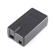
I just got the IR flash in the mail. Totally awesome. This is the one I bought:
It is a bit bigger than a soda can, so mounting it on a vehicle would be tricky, but that is another bridge to cross. All alone it might work as a speed camera photo blocker! It is weatherproof, powered by 6V DC, and has a photo sensor to detect a flash. I don't know what the sensitivity of the photo detector is, so I'll experiment with it. Eventually it will need a 12V to 6V regulator to run off the car battery.
If it isn't bright enough, I can boost the power and risk shortening it's life. There is a photocell on top that must turn it off in the daylight. I'll have to tape over that.
Here is the plan for the prototype for field tests.
- A cluster of the photodiodes SFH313FA, SFH314, SFH 309 P.
- An Arduino microcontroller to monitor the phototransistors for a sharp pulse.
- The Arduino will run a timer and filter out and only respond to flash signatures, and ignore sunlight, etc
- The Arduino will drive a small LED when a flash is detected which will be taped to the photo trigger of the IR flash. That way I don't have to modify the flash yet. Eventually I could drive it directly.
- The IR flash unit will either shine on the license plate or point at the camera. Field trials will determine what works best
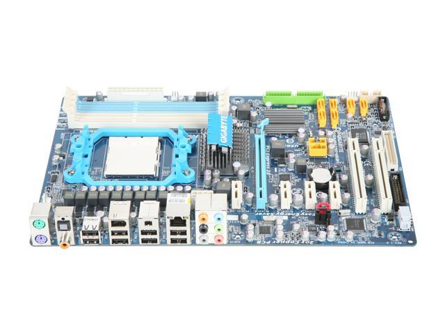
The Arduino is an easy to use microcontroller you can buy just about anywhere for $20-25, even Amazon.
You just download the software, plug in the USB and load the program from your PC. I'm using an Arduino Uno. Any of the versions Leonardo, Deuminalove, etc will work.


While I wait for the LED's to come in the mail, I decided to pop the batteries into the IR flash and take a picture of it, just to see what kind of flare I'd get. The first results were disappointing, but I think I can explain the result.
I took the photo inside in a brightly lit office. I used my Motorola android phone as the camera. I set up the sensor that came with the flash to point towards the camera. I turned the unit upside down so the daylight sensor was covered up, thinking that would turn off the flash since the lights were on.
First try the flash didn't even fire. It looks like it is glowing, but I'm convinced that is just reflection of the camera flash. The sensor is the wire on top of the flash.
I took the wire from the sensor and put it over the camera flash. Took a picture. Nothing.
Tried again, this time I got a glow. Perhaps I just messed up the first time. My finger is blurring the photo because the flash sensor is being held over the camera flash which is right next to the lens.
The results are not what I'd hoped yet. I pretty much proved I have to build the Arduino flash sensor on the front end to detect the camera flash. The provided sensor is not sensitive enough. Also my cell phone camera has a preflash sequence which may be making the slave misfire. The flash may be over by the time the picture snaps. Lets hope so, because otherwise the flash is very weak, worse than my homebrew LED array I used in my other post. I can always jack up the power an risk burning out the LEDs once I'm sure I'm triggering it right.
Better get working on the Arduino code...
I'm a little rusty on manually setting the Arduino AVR timers, so I'm going to just use the TimerOne libraries at
http://playground.arduino.cc/Code/Timer1
Downloaded the zip file, and copied the TimerOne folder into the arduino software libraries folder
C:\Users\xxxxx\Downloads\arduino-1.0.1-windows\arduino-1.0.1\libraries
Now I can also see the examples and the compiler finds the library
I need to know how long a camera flash is, so I know what rate I have to sample the phototransistors.
http://electronics.howstuffworks.com/high-speed-photography2.htm
this page says high speed photography
Sufficient flash durations can be as short as 30 microseconds
http://en.wikipedia.org/wiki/Flash_(photography)
The flash duration is typically described with two numbers: t.5 is the length of time for which the flash impulse is above 0.5 (50%) of the peak intensity, while t.1 is the length of time for which the impulse is above 0.1 (10%) of the peak[3] (t.3 of course, would be above 30%). For instance, t.5 can be 1/1200 sec whereas t.1 can be 1/450 sec for the same flash at the same intensity. For a small flash controlling intensity by time, the t.5 and t.1 numbers decrease as the intensity decreases. On flash units controlling intensity by capacitor charge, the t.5 and t.1 numbers increase as the intensity decreases (i.e. takes longer for the capacitor to discharge to that point). These times become important if a person wants to freeze action with the flash (as in sports).
http://www.paulcbuff.com/sfe-flashduration.php This site has a lot of info on xenon flash tubes. He quotes flash durations anywhere from 1/500 to 1/10,000 of a second
http://www.scantips.com/speed2.html says similar stuff. When the flash is lower power, it gets shorter.
I'm going to assume the speed camera has a badarse flash and I need to detect a 50us to 2ms pulse and respond almost instantly. The arduino analog inputs sample at about 10kHz, or 100us per sample.
http://www.digikey.com/us/en/techzone/microcontroller/resources/articles/arduinos-analog-functions-how-to-use-them.html. This is not really as good as I'd like. The plan was to have the Arduino sample the phototransistor looking for a sudden rise in intensity and fire the flash. I was hoping to use the analog inputs because that way I can subtract out any baseline ambient illumination. I can accomplish the same thing by AC coupling to a digital input. I'll probably have to try both approaches.
I'll start with a basic interface of the phototransitor the arduino.
I'm starting with the SFH309P because it is a wide angle detector.
http://catalog.osram-os.com/media/_en/Graphics/00042763_0.pdf
It says that it has a max current of 15mA, so I'll try a 1K resistor as the load. That is 5V/1K = 5mA. A bigger resistor will get me more sensitivity, but may saturate in daylight.
The two basic methods are here:
http://hades.mech.northwestern.edu/index.php/Photodiodes_and_Phototransistors
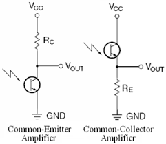
They have opposite polarity when exposed to light. The one on the right is an emitter follower which has a gain of 1. The one on the left is an amplifier. I'm going to try that with the 1K resistor. Datasheet says I'll get a 5us rise time, which should be plenty fast.
Hooked it up to the Arduino. Vout on the circuit at the above left goes to A0 on the arduino. Plug in the serial port and download the built in example example sketch "AnalogInOutSerial" to the Arduino.
The emitter is the long lead on the phototransistor, the one with the arrow in the circuit diagram.
Also hooked an LED in series with a 1K resistor to Arduino pin 9 to serve as an indicator light.
Opening the serial monitor I can see the values change when I turn on my workbench light, and the LED gets brighter when the light is on. I have basic functionality! I'm getting better response from the SFH314. I've got both on the board.
Now to write the code to detect flashes. Two possible approaches. Subtract each sample from the previous sample (differentiate the signal) and look a big positive delta signal. Or compute a long term average and subtract each sample from that. It all depends on what kind of noise there is in the samples.
I modified the code to subtract successive samples and print to the serial monitor only when a flash is detected. Took a picture at close range and bingo, flash detected! An LED lights to indicate a flash, this will be used to trigger the external flash.
Here is the Arduino sketch code:
/*
/*
Phototransistor flash detector
The circuit:
* phototransistors connected in parallel to analog pin 0.
Collectors go to pin A0, emitters go to Ground
2.2K Resistor between pin A0 and +5V
*/
// These constants won't change. They're used to give names to the pins used:
const int analogInPin = A0; // Analog input pin that the phototransistor is attached to
// Pin 13 has an LED connected on most Arduino boards.
int led = 13;
volatile long sensorValue = 900; // value read from the phototransistor
int previousSensorValue=0; // previous value from the input
int deltaSensorValue=0; // change in sensor value
int previousDeltaSensorValue = 0; // change last time
int outputValue = 0; // value output to the PWM (analog out)
int threshold = 30; // amount the input has to change to detect a flash
volatile long averageLevel = 900; // variable to store the integrated average background level
boolean flashDetected = false; //flag that a flash was detected
void setup() {
// initialize serial communications at 9600 bps:
Serial.begin(9600);
pinMode(led, OUTPUT);
}
void loop() {
// save the last values
previousSensorValue = sensorValue;
previousDeltaSensorValue = deltaSensorValue;
// read the analog in value:
sensorValue = analogRead(analogInPin);
// calculate the amount of change
deltaSensorValue = previousSensorValue - sensorValue;
// Leaky integrator to store average background level
averageLevel = ( 999 * averageLevel + sensorValue)/1000;
// print the results to the serial monitor
// filter out multiple triggers on the same rise time
if ((deltaSensorValue > threshold ) & (previousDeltaSensorValue < threshold) ) {
Serial.print("Flash Detected! Delta = ");
Serial.print (deltaSensorValue );
Serial.print ("\n");
flashDetected = true;
}
if ((averageLevel-sensorValue) > threshold) {
Serial.print("Alternate Method Flash Detected! Delta = ");
Serial.print (averageLevel-sensorValue);
Serial.print ("\n");
flashDetected = true;
}
//output a pulse on pin 13 (LED also lights) when a flash is detected
if (flashDetected) {
flashDetected = false;
digitalWrite(led, HIGH) ;
delay(10);
digitalWrite(led,LOW);
}
// wait before the next loop
// for the analog-to-digital converter to settle
// after the last reading:
// ***** shortened significantly to speed up the loop
//delayMicroseconds(50);
}
Here is the lash up. On the left is the IR flash. On the lower right is the Arduino. On the breadboard you can see four phototransistors in a parallel array with a 2.2K load connected to pin A0. Pin 13 on the Arduino is connected with a 100 ohm resistor to a LED that is taped together to the flash sensor of the IR flash.
In this video I tickle the phototransistors with a laser pointer, and you can see the IR flash fire. The flash result on the video is underwhelming to say the least. The LED's don't blind the cell phone video when they fire.
So far I've taken several flash photos of the setup, and the flash picture (I am still using a cell phone) misses the IR flash firing. I must be firing the IR flash late, no other logical explanation.
I set up the scope to trigger on an edge and capture the circuit's response to a couple different flashes to see what kind of timing I'm dealing with.
The circuit is just the common emitter amp with a 2.2K load, 5V supply from the Arduino and four SFH314 photo transistors in parallel.
Some interesting results. My cell phone does a double flash (It is a Motorola Droid 4). The trigger catches two The circuit is an inverter, so the onset is the fall time. I measure 225us as the rise time. There are two 100ms pulses 100ms apart. 1/10 of a second. Way way slower than the web page says a real flash should be. I shouldn't be wasting my time using a cell phone LED flash for these experiments
I pulled out my real camera. A fairly high end point and shoot:
Canon PowerShot SX260 HS 12.1 MP CMOS Digital Camera
It has a flash that pops up, which I don't think is an LED, but I can't find much information on what exactly it is. I got very different results. This time I got a 200us pulse with a 1.4us rise time. Completely different ball park. The fall time was much more like what the earlier web page said it would look like. 1/5000 of a second. The shutter speed range is quoted as 15-1/3200 of a second.
To catch a flash and shutter speed like that I'm going to need to sample at least every 100us (10kHz) and respond in 100us. That still seems doable. I did notice that this camera also does a double flash.
Next I set up the scope for two channels and measure the flash and the firing of the LED on the output of the Arduino to see the response time. Here is the cell phone flash and the resulting trigger pulse generated by the Arduino. Remember the falling edge is the onset of the flash. Seems like the response is plenty fast. But the cell phone is not a good test because it must have such low sensitivity that it is taking a picture for 100ms and the triggered flash is only 10ms. Much less light.
Here is what it looks like with the Canon Powershot SX260 flash. You can see the double trigger here, 80ms apart. But the flash pulses are much shorter.
Zooming in you can see I have about a 600us delay from the onset of the flash to the response edge. That is much too slow. Gotta speed up the Arduino.
I thought I'd share the picture the camera took on the above capture. You can see in the middle of the messy desk the IR flash extender. You aren't blinded. I know the IR flash is working because I can see it fire with the cell phone video camera. Oh well the Wright brothers didn't fly the first time either.
I think what I need to do next is to program the Arduino to tell me the information that the scope shows. Reliably detect the flash, measure it's duration and report if it is a double pulse.
The double pulse is used by the camera to set the exposure first, then take the picture. I suppose a speed camera could be doing the same thing. The flashes are 80ms apart. A car travelling 60 miles per hour goes 88 feet per second. So it would have moved 7 feet between the pulses. I've observed red light cameras and your eye can tell that two photos are being taken. You might be able to see the double flash. 25 frames per second is 40ms, a rate at which you can see some flicker.
The double flash might be a way to exploit the camera and ruin the photo. If the flash fires on the first pulse, but ignores the second, the exposure might be wrong. I'm going to strap some photo detectors to the Arduino and rewrite the code and take the unit outdoors to observe a camera flash and a speed camera conveniently located near my home.
I think the bump on top is the actual radar, the left hand is a monster flash, 6-8" in diameter with a circular flash bulb in it. The camera lens looks dark and non reflective, clearly it has a well AR coated lens and is as big in diameter as any camera lens I've seen. I've seen inside these boxes and most of the contents is auto batteries which they come and swap out once a week or so.
The flash is on the left, you can just make out the circular bulb of the flash.
Back to the lab. The next step is to get my Arduino flash timer circuit working. I'm going to put a photo transistor on the IR flash and use the scope to measure the timing between the original flash detection and the firing of the IR repeater flash.
I repeated the measure of the delay time through the Arduino that I'm using as a flash detector. I used two channels of the scope. Channel 1 is attached to the phototransistor at the Arduino's input. Channel 2 is attached to another phototransistor that is placed next to the LED at the Arduino's output. The arduino program (above) lights the LED for 10ms when a flash is detected. I put a mouse pad over the second phototransistor so it won't also detect the flash.
Here is the arduino and the LED's and scope probes.
Here is the response. You can see the 10ms wide pulse on the blue trace that is the Arduino output in response to the yellow trace.
Blow it up and you can see the blue trace falls 575us after the yellow. That is 1/1700 of a second. A little slower than I'd like. I will have to look at the Arduino program to see if I can speed up the response.
Next I have to see how long the IR flash takes to respond. I'll need a phototransistor placed near it's output. My first attempt didn't work, I tried to use the original photodetector for both the first flash and the flash back, expecting two pulse. The pulse width from my cell phone camera is too wide and I can't see the responding flash pulse. I know the IR flash is working because I can push the test button on it and get a response from the photo diode.
I ditched the photosensor that came with the game IR flash. It was very insensitive, an LED driven by the Arduino taped face to face wasn't reliably triggering it. Instead I found an old DC power cord that fit and found that shorting the two pins triggered the flash. I get a 100ms wide pulse out of the flash. Here is a scope shot of the IR flash captured by a phototransistor.
I used a random transistor to connect the Arduino to the flash sensor wires like this:
Here it is on the breadboard with the scope probe on the phototransistor output. Going off to the lower left is the cable to the sensor input of the IR flash. When the Arduino fires it turns on the 2n7000 and shorts the two leads. This seems to work.
Another phototransistor is attached to the scope in front of the IR flash. I seem to get lots of signal from it when the flash fires. The blue trace below is the first phototransistor responding to the flash on a cell phone. The yellow trace is the second phototransistor in front of the IR extender flash.
Booo! The IR extender flash is slow as a pig. The delay is a total of 10.6ms. The 600us is the Arduino delay, and the rest is the built in delay of the IR flash. A nice round 10ms. The flash stays lit for 100ms after that. 10ms is a dismal 1/100 of a second. No wonder it is so slow that the high speed camera misses it. I may have to crack open the IR flash and redo the circuit to speed it up. To think I was worried about the 600us delay in the Arduino.
None the less, I rewrote the Arduino code to make the loop and response time as fast as possible. Moved the serial writes out of the critical path. This version is WAYYYYYY better. Now the delay is down to 100us from 600us. This is just the Arduino delay from the phototransistor input to the 2n7000 turning on at the output.
Here is the new code for the Arduino. Stripped out all the useless stuff and eliminated everything between the detection and the turn on of the output.
/*
/*
Phototransistor flash detector
The circuit:
* phototransistors connected in parallel to analog pin 0.
Collectors go to pin A0, emitters go to Ground
2.2K Resistor between pin A0 and +5V
* 2N7000 gate tied to pin 13, S to ground, D to flash sensor plug pin.
*/
const int analogInPin = A0; // Analog input pin that the phototransistor is attached to
// Pin 13 has an LED connected on most Arduino boards.
int led = 13; // also used to connect IR flash (gate of 2N7000)
//
volatile long sensorValue = 900; // value read from the phototransistor
int previousSensorValue=0; // previous value from the input
int deltaSensorValue=0; // change in sensor value
int previousDeltaSensorValue = 0; // change last time
int threshold = 30; // amount the input has to change to detect a flash
boolean flashDetected = false; //flag that a flash was detected
void setup() {
// initialize serial communications at 9600 bps:
Serial.begin(9600);
pinMode(led, OUTPUT);
}
void loop() {
// save the last values
previousSensorValue = sensorValue;
previousDeltaSensorValue = deltaSensorValue;
// read the analog in value:
sensorValue = analogRead(analogInPin);
// calculate the amount of change
deltaSensorValue = previousSensorValue - sensorValue;
// print the results to the serial monitor
// filter out multiple triggers on the same rise time
// minimal stuff in this statement to speed up response.
if ((deltaSensorValue > threshold ) & (previousDeltaSensorValue < threshold) ) {
digitalWrite(led, HIGH) ;
flashDetected = true;
}
//output a pulse on pin 13 (LED also lights) when a flash is detected
if (flashDetected) {
flashDetected = false;
digitalWrite(led, HIGH) ;
delay(10);
digitalWrite(led,LOW);
Serial.print("Flash Detected! Delta = ");
Serial.print (deltaSensorValue );
Serial.print ("\n");
}
}
Meanwhile what I'm going to do next is solder up the photodetector circuit on an Arduino project board, add and LCD so I know what happened, and go in the field and detect some flashes from the speed camera.
I'm going to use some parts I have lying around to make the field version. There are LCD protoboards for sale but I'm going to use what I have on hand.
Hooking up the LCD 16 pin connector & the Arduino pin assignments:
This is my favorite pinout for the Arduino LCD because it keeps all the LCD pins in the same connector.
* NOTE pinout slightly modified from standard to ease the board wiring
* LCD RS pin 4 to Arduino digital pin 7 (examples use 12)
* LCD Enable pin 6 to Arduino digital pin 6 (examples use 11)
* LCD R/W pin 5 to gnd (always write)
* LCD D4 pin 11 to Arduino digital pin 5
* LCD D5 pin 12 to Arduino digital pin 4
* LCD D6 pin 13 to Arduino digital pin 3
* LCD D7 pin 14 to Arduino digital pin 2
* LCD pin 3 to annode of diode to ground and pin 3 also to resistor to 5V supply
* this is a trick to get 0.5V using a diode drop, avoiding a potentiometer
* LCD pin 16 backlight gnd to gnd
* LCD pin 15 backlight supply to Arduino digital pin 12
Did a pretty bad hack job of soldering the wires and headers on the proto board. I tend to rush things in this stage since neatness doesn't really count. Plus I need a new soldering iron, my tip is rubbish. Lashed it up and ohmed it out to make sure it was right.
Top of the board before putting the LCD onto the header in the middle. Ignore the extra pushbutton switch, I recycled the proto board and it was from a previous project. I need to remove it.
Bottom of the board.
A little test program to make sure I wired up the LCD right , basically the LCD arduino example with the pins moved a little.
// include the library code:
#include <LiquidCrystal.h>
// initialize the library with the numbers of the interface pins
LiquidCrystal lcd(7, 6, 5, 4, 3, 2);
void setup() {
pinMode(12, OUTPUT); // the LCD backlight LED
// set up the LCD's number of columns and rows:
lcd.begin(16, 2);
// Print a message to the LCD.
lcd.print("hello, world!");
digitalWrite(12, HIGH) ; // the LCD backlight LED
}
void loop() {
digitalWrite(12, HIGH);
// set the cursor to column 0, line 1
// (note: line 1 is the second row, since counting begins with 0):
lcd.setCursor(0, 1);
// print the number of seconds since reset:
lcd.print(millis()/1000);
}
Here is the LCD on the protoboard, stacked on top of the Arduino, running the above program. Woot! it's alive and displaying most of hello world. It is a small 8x2 display.
Next I will solder on the real stuff, the photo transistors. LCD was a 2 hour detour. Here are the phototransistors soldered in. I have upgraded to two arrays, one array of 6 and one array of a single detector. This is to cover a wider range of lighting conditions. I'll update the schematics to show this.
One last step, need to add the 2N7000 switch to the output and solder on the flash cable. Lousy soldering.
Arduino sketch is updated to support the LCD and the two separate detector arrays with different sensitivities. LCD backlight blinks when a flash is detected.
/*
Phototransistor flash detector/repeater program
The circuit:
* phototransistors connected in parallel to analog pin 0.
Collectors go to pin A0, emitters go to Ground
2.2K Resistor between pin A0 and +5V
* 2N7000 gate tied to pin 13, S to ground, D to flash sensor plug pin.
* NOTE LCD pinout slightly modified from standard to ease the board wiring
* LCD RS pin 4 to Arduino digital pin 7 (examples use 12)
* LCD Enable pin 6 to Arduino digital pin 6 (examples use 11)
* LCD R/W pin 5 to gnd (always write)
* LCD D4 pin 11 to Arduino digital pin 5
* LCD D5 pin 12 to Arduino digital pin 4
* LCD D6 pin 13 to Arduino digital pin 3
* LCD D7 pin 14 to Arduino digital pin 2
* LCD pin 3 to annode of diode to ground and pin 3 also to resistor to 5V supply
* this is a trick to get 0.5V using a diode drop, avoiding a potentiometer
* LCD pin 16 backlight gnd to gnd
* LCD pin 15 backlight supply to Arduino digital pin 12
*/
// include the library code:
#include <LiquidCrystal.h>
// initialize the library with the numbers of the interface pins
LiquidCrystal lcd(7, 6, 5, 4, 3, 2);
const int analogInPin0 = A0; // Analog input pin that the 6 phototransistors are attached to
const int analogInPin1 = A1; // single photo transistor input
int led = 13; // also used to connect IR flash (gate of 2N7000)
int backlight = 12; //LCD backlight
volatile long sensorValue = 900; // value read from the phototransistor
int previousSensorValue=0; // previous value from the input
int deltaSensorValue=0; // change in sensor value
int previousDeltaSensorValue = 0; // change last time
int threshold = 10; // amount the input has to change to detect a flash
int flashCount =0; //number of flashes detected
void setup() {
pinMode(backlight, OUTPUT); // Set up LCD backlight
digitalWrite(backlight, HIGH) ; //Turn on LCD backlight
// set up the LCD's number of columns and rows:
lcd.begin(8, 2);
// Print a message to the LCD.
lcd.print("Hello!");
// initialize serial communications at 9600 bps:
Serial.begin(9600);
pinMode(led, OUTPUT);
delay(3000);
lcd.clear();
digitalWrite(backlight, LOW);
}
void loop() {
// save the last values
previousSensorValue = sensorValue;
previousDeltaSensorValue = deltaSensorValue;
// read the analog in values:
// adding the sensitive and insensitive inputs allows the insensitive to work
// when the sensitive is saturated.
sensorValue = analogRead(analogInPin0) + analogRead(analogInPin1);
// calculate the amount of change
deltaSensorValue = previousSensorValue - sensorValue;
// print the results to the serial monitor
// filter out multiple triggers on the same rise time
// minimal stuff in this statement to speed up response.
if ((deltaSensorValue > threshold ) & (previousDeltaSensorValue < threshold) ) {
//trigger external flash immediatly
digitalWrite(led, HIGH) ;
flashCount++;
digitalWrite(led, HIGH) ;
delay(10);
digitalWrite(led,LOW);
digitalWrite(backlight, HIGH);
Serial.print("Flash Detected! Delta = ");
Serial.print (deltaSensorValue );
Serial.print ("\n");
lcd.setCursor(0, 0);
lcd.print("Flash");
lcd.print(flashCount);
// set the cursor to column 0, line 1
lcd.setCursor(0, 1);
lcd.print("Level");
lcd.print(deltaSensorValue);
lcd.print(" ");
digitalWrite(backlight, LOW);
}
}
Last check to measure the response time to make sure the extra code didn't slow down the response. Interesting. Doing two analogReads of the two sensor arrays in one line adds 100us to the delay time. I'll remember that if I need to speed things up later.
Delay time with reading both analog inputs and summing them, 200us
Delay time reading only analogInput 0, 100us
Here is a picture of the working unit, without the cover on: The scope probes are attached to measure the delay. Taking the picture caused the display to show the Flash detected and intensity values in the picture. Isn't that a time travel paradox? It's because of the pre-flash my cell phone uses to set exposure.
I need to drill out the cover for the phototransistors and display.
Here is the unit assembled with the cover drilled out for the phototransitors and the display. I did a crap job drilling, the plastic was hard to drill and cut. Oh well it's not a beauty contest. i got a case of giterdone.
I use a cell phone charger USB battery to power the Arduino. If found my old one was dead, so I invested in a new one. This will give me plenty of power and will just plug into the USB input on the Arduino.
This battery seems to be a bust. They must use a switching regulator. It charges a phone fine, but it makes the Arduino freak out and constantly detect a flash. I will have to drop back to using a 9V battery.
Here is the setup.
It's finally warming up outside and the detector unit is ready so it's picnic time!
Saw an article that the speed camera I'm targeting prints 82 tickets a day over a 14 hour period of operation. That means between 5 and 6 and hour. I'll have to sit at the speed camera for a while to see it go off. Not posting the link to the article because of obvious reasons. Apparently before the camera there were >1000 a day, and the first month of operation there were 216.
First trip to the field is just to use the flash detector without the flash to make sure I can detect the flash from the speed camera. I happen to know exactly where the car is when the camera triggers. I have a photo of my car on the ticket to use as reference.
I think I will open a new post on the field tests, since this post is pretty deep into electronics and has gotten kind of long. I'll come back and add the flash modifications to this post but for now I'm moving to another post for the detector testing.
Click here for more...
http://blog.workingsi.com/2013/03/field-testing-ir-speed-camera-blocker.html


.jpg)