Search This Blog

Wednesday, July 24, 2013

Arduino - avrdude: stk500_getsync(): not in sync: resp=0x00 error


This error happens whenever the Arduino IDE software can't talk to the Arduino board.
Code compiles and it gets to 90% on the progress bar and hangs.  Eventually it says
avrdude: stk500_getsync(): not in sync: resp=0x00

This could have any number of causes.  Just jotting down some of the things that have gone wrong and how I've fixed them.  Not detailed instructions, detail is everywhere on the web.


  • Is it plugged in?  Right port selected on Tools->Serial->Port.  Try a different cable.  Is the power light on the Arduino green?  Are the TX/RX lights flashing during upload?
  • Make sure the Arduino drivers are installed on your machine.  This usually happens when you load the software, but not always.
  • Go to the Computer->System->Device manager and find the arduinos.   Are they properly recognized?  if not, right click and update the driver with the Arduino drivers in the download
  • People often claim hitting the Arduino reset right after compilation will make it work.  That has never worked for me.
  • Sometimes the bootloaders get corrupted on the AVR chip.  To fix that you should get a AVR MKII ISP programmer from Digikey. http://www.digikey.com/product-search/en/programmers-development-systems/in-circuit-programmers-emulators-and-debuggers/2621880?k=avr%20mkii%20isp.   They are $37 but if you do enough Arduino work it is worth it.   There are ways to hack this up with another Arduino, but I've never tried it.   The Tools menu has settings for which programmer you have and to burn the bootloader.  You connect the programmer to the USB and plug it into the Arduino ISP header.  You have to supply 12V to the Arduino from the power jack.   Disconnect the Arduino USB connection and burn the bootloader.  Then upload your program with the programmer using the File->Upload using programmer.   Unplug the programmer from the Arduino and it should work normally.
  • Using the programmer you can just load the program through the ISP, without burning the bootloader, and sometimes everything will begin to work again.   Other times it will program fine, but the serial interface will still not work.  
  • I had two Arduino boards which none of the above worked.  The chip is probably dead..  I decided to try replacing the microcontrollers.   Order the ATMEGA328P-PU-ND http://www.digikey.com/product-search/en?WT.z_header=search_go&lang=en&site=us&keywords=ATMEGA328P-PU-ND&x=-1691&y=-51 for $3.16.   I pulled the old chip out of the socket and replaced it.  I burned the bootloader using the Arduino software.   Now it works!  Board is saved.

Friday, July 19, 2013

Nintendo 3DS power jack repair

My daughter's Nintendo 3DS wouldn't charge well any more.  The power plug on the 3DS was obviously very worn out and bent looking, and even the charging base wasn't working very well.  The charging light would flicker yellow and lots of fiddling might make it charge if you were lucky.

It was clear that there was a broken or barely hanging on electrical connection in the power jack.

I put this off a while, thinking it would be hard, but it turned out to be a really easy repair.

You can buy replacement jacks on ebay and amazon for <$7 including shipping.  Make sure to buy it somewhere from a US vendor, not from a vendor shipping from China/Honk Kong.  You would still get it, but it will take you weeks.

Found them on amazon.
Power Jack Socket Dock Connector Charger Charging Port Nintendo 3DS Replacement

Bought this replacement jack off ebay for $6.35, free shipping.  Came in two days!
http://cgi.ebay.com/ws/eBayISAPI.dll?ViewItem&item=330957509059

Power Jack Socket Dock Charger Charging Port Replacement for Nintendo 3DS N3DS

Watched this video.  Not bad this kid shows you how to get the cover off.
how to fix nintendo 3ds charging port - YouTube

You need a really small Phillips head and optionally a plastic pry tool.  If you are careful or use your fingernail you don't need the pry tool.  You can buy them on eBay for pennies.

After the 4 screws on the battery cover, There are nine screws and one on the game slot you have to take out.   They are very small and were in really tight.  A good screwdriver is needed, and press hard.


Take out the SD card and battery and any games and the bottom half of the DS pulls right off.


Watch out for the flex cables, just leave them connected and don't pull them.

I found the power jack actually just sitting in place.  All of the solder connections were broken loose and I could just pull it off.   The new connector went right on top of where the old one was.


I used a soldering iron and solder to attach the 6 tabs to the pads.  It's obvious how it goes.  My solder job was crap because it's small and my iron was big, however it was still no problem.

Put the lid back on, screws back in, battery, SD card, cover.  Powered up.  Ba da bing.  Plugged in the charger.  Yellow light.  Win!

This is a really easy repair.  If the connector had not been obviously broken, I would have had to use the soldering iron and the little vacuum desoldering tool to remove it.   Available at radio shack.  Luckily I didn't have to do any desoldering.


Monday, July 15, 2013

Spoofing OBDII to pass emissions test

This is a bad idea, but I just wanted to get it out of my system.


Today I had to take my old Honda for a state emissions test.   The test consists of looking under your car with a mirror, and plugging in the OBDII for about 2 minutes.  They may have some sensors for the exhaust gases, but it's not obvious.   It's my understanding that they poll the OBDII for any error codes, and that is just about it.   I passed, but had to wait in line long enough to make me think subversive thoughts.

I was reminded of the work I did years ago building an OBDII reader.  But how hard would it be to make a spoofed OBDII device?   It seems like it would be pretty easy to disconnect the OBDII and put a micro-controller behind the OBDII connector to read back a clean bill of health.

The usual disclaimer, I would never do such a thing and I don't advocate any one else do it.  But as an intellectual exercise I thought I'd look into the feasibility.   I wonder if there are protections against this sort of thing?

There are no new ideas under the sun, so a little googling found some people thinking of the same thing:

http://forums.nasioc.com/forums/showthread.php?t=753331
http://grassrootsmotorsports.com/forum/grm/learn-me-obd-ii-emulation/58941/page1/
http://my.is/forums/f114/passing-obd2-emissions-standalone-339716/index5.html
http://forum.miata.net/vb/showthread.php?t=143853

Ease Diagnostics makes an OBD-II emulator - 
http://www.obd2.com/emissions/data/emissions_ver_test.htm
Used for testing the emissions testers.  They have this little box telling you why you can't use if for spoofing:

SECURITY FEATURES
To prevent the EASE OBD II Verification Tester from being substituted as a "clean" vehicle in an emissions inspection, we have built in the following security features.  
  • The controller ID is permanently set to $FD.  This value is not an acceptable controller ID.
  • The number of PIDs is always 32.  On an actual vehicle this would mean all the PIDS were supported.  This is not likely to happen. 
  • The AC Sys Refrig I/M Monitor is always Supported and Not Complete. No vehicle currently supports this I/M monitor. 

Looks like the OBDII has some vehicle information, rpm, etc.  All which would be easy to duplicate.  So the first step would be to read your present OBDII, clone the information, and write it back to the spoofer.

One of my raspberry PI's might be best, because it has lost of memory/disk for stored values and GPIO to write a bit banged serial interface, and you can connect a keyboard, display and mouse for the programming phase.   An arduino might be able to pull it off, but I suspect it would require two programs.  One to read and one to spoof.

This page has some info on what the emissions test is looking for
http://www.scangauge.com/tips-and-tricks/finding-incomplete-obdii-tests-using-the-scangauge-ii/

I'll put this idea on the shelf for now and see if I decide to build it later.

Sunday, July 14, 2013

LCD system monitor for PC case bling using Arduino

This post is about a project to build a CPU/system monitor display for the front of a Windows desktop computer. Lights that get brighter as the CPU load increases.  A little fun and bling for the new machine.


I'm building a new high end desktop PC, and due to a delay in getting the processor shipped to me I've been wasting time thinking of what accessories to fill up those unused 5.25" bays.

I saw some widgets with LCDs to display temperature and fan speeds, etc.  However after reading reviews I'm not thrilled with any of them.   Additionally they don't read the real temperatures, they have probes you glue on.


That got me thinking of a quickie project that would be fun.   I'll make a panel LCD myself,   I'd like to display the CPU load, or other parameters, and temperatures if I can.  I know it's fairly hard to pull the temperatures from motherboards due to the wide variety of designs.

The basic design will be this.  I'll use an Arduino with an LCD plugged into either a USB port or onto a USB header on the mother board.   It will be a fairly simple serial client that displays whatever text you send it.
Running on the PC will be a Java program feeding info to the USB serial com port.   The Java program will pull the CPU load and System temperatures and format it for display.   I could do color changes, whatever to make it fancy.

The first task is to access the desired information from the Java program running on the Windows PC.

Some useful posts

  • http://stackoverflow.com/questions/47177/how-to-monitor-the-computers-cpu-memory-and-disk-usage-in-java
  • http://stackoverflow.com/questions/634580/cpu-load-from-java
  • http://sellmic.com/blog/2011/07/21/hidden-java-7-features-cpu-load-monitoring/


Some info can be pulled from within Java, but it is fairly limited.  I tried this code pasted into a little netbeans program

OperatingSystemMXBean OS = ManagementFactory.getOperatingSystemMXBean();    
        jLabelCPUs.setText("Number of CPUs: "+ Integer.toString(OS.getAvailableProcessors())+ " " +OS.getArch());;
        jLabelLoad.setText("CPU load: "+ Double.toString(OS.getSystemLoadAverage()));
     
The OS.getSystemLoadAverage() always Returns -1.   A little more reading reveals that this doesn't work on Windows.  Not definitive but discouraging.   The CPU architecture commands do work though.

Instead I thought I'd run a windows command line program from within Java and pull the output.  This approach worked much better.

http://stackoverflow.com/questions/9097067/get-cpu-usage-from-windows-command-prompt

There are two basic approaches.  wmic and typeperf.  Entered these commands into a cmd window and got back a string of the CPU load.   Both have some pretty obscure command arguments.
        wmic cpu get loadpercentage
        typeperf -qx "\Process" > config.txt typeperf -cf config.txt -o perf.csv -f CSV -y -si 10 -sc 60

Now to embed this in Java and get the output back to the Java program.
This Java code runs the cmd line wmic.

try {
            Process p = Runtime.getRuntime().exec("wmic cpu get loadpercentage");
} catch (IOException ex) {
            System.out.println("cmd line failed");
            Logger.getLogger(BlingGui.class.getName()).log(Level.SEVERE, null, ex);
}

Looking for how to get the output back, I see I just gotta use buffered stream to read it:

Back to polishing up the windows cmd line commands to get the data I want.

Wmic is awesome!   I can get more than cpu load.  All sorts of process and machine info.
wmic cpu get currentClockSpeed
wmic cpu get loadpercentage

Typeperf is also very useful.
http://technet.microsoft.com/en-us/library/bb490960.aspx

This command gives processor and memory usage in running 1 second intervals.  Awesome.
typeperf "\Memory\Available bytes" "\processor(_total)\% processor time"


This makes just one sample, also seems a little slow to respond
typeperf -sc 1 "\processor(_total)\% processor time"
typeperf command format is a mess to escape in Java, but got it to work like this:
Process p = Runtime.getRuntime().exec("typeperf \"\\processor(_total)\\% processor time\" ");
This makes just one sample at a time.
typeperf -sc 1 "\processor(_total)\% processor time"

Here is the output of typeperf writing to a hack GUI in Java. The yellow is the CPU%.  Obviously haven't done the formatting yet.   Making progress!


I wasted some more time looking for how to get the temperature command line, and it is not easy. I'm avoiding using somebody else's freeware program like CPUID or speedfan. Both of which work but won't get me to my goal. I'm going to stick with CPU load, memory and frequency data for the prototype.

A little more work and I have a Java performance meter program. Grabbed the cmd line output, did some string manipulation and formatting.  I haven't added the serial client stuff yet to talk to the Arduino yet.  This demos all three methods.  Java commands, wmic and tyeperf commands.  The typeperf is the one running the progress bar.


The executable is here: https://code.google.com/p/arduino-java-xyzcnc/downloads/list
This is the gist of the code, minus the GUI stuff.

 public BlingGui() {
        initComponents();
        this.setVisible(true);
        OperatingSystemMXBean OS = ManagementFactory.getOperatingSystemMXBean();
        
        jLabelCPUs.setText("Number of CPUs: "+ Integer.toString(OS.getAvailableProcessors())+ " " +OS.getArch());;

      
        Timer t_update = new Timer(10000, new ActionListener(){
            private String t1;
            @Override
            public void actionPerformed(ActionEvent e){
                try {
                    Process w1 = Runtime.getRuntime().exec("wmic cpu get CurrentClockSpeed");
                    BufferedReader stdInput1 = new BufferedReader(new InputStreamReader(w1.getInputStream()));
                    BufferedReader stdError1 = new BufferedReader(new InputStreamReader(w1.getErrorStream()));
                    
                    while ((t1 = stdInput1.readLine()) != null) {
                        if(t1.length()!=0)
                            if( Character.isDigit( t1.charAt( 0 ) )) jLabelFreq.setText("Clock: "+ t1.trim() +" MHz");
                    }
                    

                } catch (IOException ex) {
                    System.out.println("cmd line failed");
                    Logger.getLogger(BlingGui.class.getName()).log(Level.SEVERE, null, ex);
                }
                    
                }
            });
            t_update.start();
        
        
        try {
            
            // execute windows command line:  typeperf -sc 1 "\processor(_total)\% processor time"     
            Process p = Runtime.getRuntime().exec("typeperf \"\\processor(_total)\\% processor time\" ");
            
            BufferedReader stdInput = new BufferedReader(new InputStreamReader(p.getInputStream()));
            BufferedReader stdError = new BufferedReader(new InputStreamReader(p.getErrorStream()));


            // read the output from the command
            System.out.println("Here is the standard output of the command:\n");
            String s;
            while ((s = stdInput.readLine()) != null) {
              s = s.replace("\"", "");
              String[] sArray = s.split(",");
              s = sArray[sArray.length-1].trim();
              jLabelLoad.setText("CPU Load: " + s + "%");
              
             try {
                jProgressBarCPU.setValue( Integer.valueOf(s.indexOf('.') ));
                double dd = Double.valueOf(s);
                int gg = (int) dd;
                jProgressBarCPU.setValue( gg);
                if (gg<33) jProgressBarCPU.setForeground(Color.green);
                else if (gg<66) jProgressBarCPU.setForeground(Color.orange);
                else jProgressBarCPU.setForeground(Color.red);
             } catch (Exception e) {
                //Sometimes this is not a number
               
             }
              
            }  
        
            // read any errors from the attempted command
            System.out.println("Here is the standard error of the command (if any):\n");
            while ((s = stdError.readLine()) != null) {
                System.out.println(s);
        }
                    
            
        } catch (IOException ex) {
            System.out.println("cmd line failed");
            Logger.getLogger(BlingGui.class.getName()).log(Level.SEVERE, null, ex);
        }    
        
    }
    

Next step is to combine this with my Arduino serial communication program to send the CPU load data to an external Arduino with LCD shown in this post:
http://blog.workingsi.com/2013/01/revisiting-arduino-control-from-pc.html
This is just for prototyping, I'll build a custom LCD unit that fits in a drive bay once I get the s/w working.

For proof of concept I did a Frankenstein and simply pasted the CPU monitor GUI class right into my serial comm tool.   That way I use that tool to find the Arduino comm port and connect, and then the CPU monitor   kicks in and sends the CPU load string information as if I were pushing the send button on the GUI.

The Arduino is just running the Examples->Liquid Crystal->SerialDisplay sketch right out of the box.
The hardware is an Ardino with a large 4x20 LCD connected just like the Arduino example says.   I won't repeat all that here.  I reused this from http://blog.workingsi.com/2011/02/arduino-lcd-countdown-clock.html.   Everybody should have an Arduino with an LCD on it lying around for emergencies.

W00t!  It works!.   Here is the PC running the serial comm tool, with the new CPU GUI below it.  On top of the screen is the Arduino/LCD displaying the CPU load every second.


Now to clean up the code and make the LCD display a bar graph instead of just number.

The Arduino code need some upgrades.
  • Sleep whenever it hasn't gotten data in a while.  Turn off the LCD backlight and blank the display.
  • Initially send a character like "AAAAA" until it's connected so the Java GUI can find it and initialize communication
  • Eventual features using the Analog pins to control some LEDs brightness or color
Here is the Arduino sketch.  I'd like to keep it simple like this.  It can also display messages as I choose if I leave the brains in the Java host side:

/*
  LiquidCrystal Library - Serial Input

This sketch displays text sent over the serial port
 (e.g. from the Serial Monitor) on an attached LCD.

 The circuit:
 * LCD RS pin to digital pin 7
 * LCD Enable pin to digital pin 6
 * LCD D4 pin to digital pin 5
 * LCD D5 pin to digital pin 4
 * LCD D6 pin to digital pin 3
 * LCD D7 pin to digital pin 2
 * LCD R/W pin to ground
 * 10K resistor:
 * ends to +5V and ground
 * wiper to LCD VO pin (pin 3)

  
 http://arduino.cc/en/Tutorial/LiquidCrystalSerial
 */

// include the library code:
#include <LiquidCrystal.h>
const int backlight = 8;   // the LED backlight is wired to pin 8

long previousMillis = 0;            //stores the last time the display got data

// initialize the library with the numbers of the interface pins
LiquidCrystal lcd(7, 6, 5, 4, 3, 2);

void setup(){
    // set up the LCD's number of columns and rows:
  lcd.begin(16, 2);
  // set up the LCD backlight
  pinMode(backlight, OUTPUT);
  digitalWrite(backlight, LOW);
  // initialize the serial communications:
  Serial.begin(9600);
  establishContact();  // send a byte to establish contact until receiver responds
}

void loop()
{
  // when characters arrive over the serial port...
  if (Serial.available()) {
    // wait a bit for the entire message to arrive
    delay(100);
    // clear the screen
    lcd.clear();
    // wake up and turn on the backlight
    digitalWrite(backlight, HIGH);
    previousMillis = millis();
    // read all the available characters
    while (Serial.available() > 0) {
      // display each character to the LCD
      lcd.write(Serial.read());
    }
  } else if (millis() - previousMillis > 10000) {
     //turn off the backlight and clear the display
     digitalWrite(backlight, LOW);
     lcd.clear();

  }
}

void establishContact() {
  while (Serial.available() <= 0) {
    Serial.println("Z");   // send an initial string
    delay(300);
  }

}

Now the display wakes up when it gets a message, and goes blank 10 seconds after the last update.  Perfect.

None of the LCD's in my drawer will fit behind a 5.25" drive bay panel.   Actually some of the tiny ones will do but I want something snazzy.
The panel on the PC is about 1 5/8 * 5 3/4, (42mm x146mm)  and the LCD will need to be smaller.   I probably will need to use a 2x20 to get the right shape, the 4x20s are too tall.
It is also clear the Arduino itself is too tall and I will have to use a right angle header to connect to the LCD.

It occurred to me that I would also like to have some connector/header on the front I can use to access a few of the pins of the Arduino so I can use it for development and whatever GPIO project I dream up.

This vacuum fluorescent one looks cool, a bit pricey at $29
20x2 Character VFD (Vacuum Fluorescent Display) - SPI interface
http://www.adafruit.com/products/347
http://www.adafruit.com/datasheets/20T202DA2JA.pdf
It also has a serial interface.  That will save pins but require the code to be changed.
Outer dimensions are 37mm x  116mm.  It will just barely fit.


http://www.adafruit.com/products/399#Downloads
This one is 36x80mm and has a three color backlight.  $14. Only 2x16 chars
RGB backlight negative LCD 16x2 + extras

Looking at digikey...

http://www.digikey.com/product-detail/en/M0220SD-202SDAR1-1G/M0220SD-202SDAR1-1G-ND/1701410
MODULE VF CHAR 2X20 5.34MM | M0220SD-202SDAR1-1G | M0220SD-202SDAR1-1G-ND | Digi-Key Corp.
$31, 116mm x 37mm, 20x2, parallel interface like I'm used to.  However price is a bit steep, not sure if VF is worth it.

Searched a while, decided the VF displays are too expensive and I like the multicolor backlight price and convenience of LCD.

Digikey has this one, looks similar to the one on Adafruit.
http://www.digikey.com/product-detail/en/NHD-0216K1Z-NS(RGB)-FBW-REV1/NHD-0216K1Z-NS(RGB)-FBW-REV1-ND/2172436
LCD MOD CHAR 16X2 RGB TRANSM | NHD-0216K1Z-NS(RGB)-FBW-REV1 | NHD-0216K1Z-NS(RGB)-FBW-REV1-ND | Digi-Key Corp.

I decided to get the Adafruit display, they say they have resistors onboard for the backlight, and it comes with a trim pot.

The display came.  I'm going to mount it in an old 5.25 bay blank plastic cover from an old PC.  Here is the display sitting on top of the plastic blank bay cover.


My plan is to wire it up just like the Adafruit tutorial
http://learn.adafruit.com/character-lcds/rgb-backlit-lcds
And to add a small header connector to some unused pins to come out the front of the PC for development projects.

I cut a hole in the plastic panel to fit the LCD with a Dremel. It didn't come out as well as I'd hoped.  I'm going to have to fill and paint or try again with another blank.   Forging forward to work out the rest of the details before wasting time remaking something that may have to change anyway.

I'm using the header pin strips that came with the LCD to connect some scrounged IDE ribbon cables to the display.  I had thought I'd connect that directly to the Arduino with another header, but the power, ground and potentiometer connections will be awkward and messy.   Plus I wanted to put the analog pins on another header that sticks out the panel so that I can use them for future prototyping projects.    So I decided to bite the bullet and use an $6 adafruit prototyping shield to serve as a patch board and the $2 headers.  These I had in my parts bin already from past projects.
Adafruit Proto Shield for Arduino PCBShield stacking headers for Arduino (R3 Compatible)
http://www.adafruit.com/products/55
http://www.adafruit.com/products/85

The IDE ribbon cables are 17 pins wide, and I need 18, so I'll take advantage of the fact that the R/W pin is grounded and just short them together on the LCD.

Here is the protoboard soldered up with the headers and pot, connecting the cable header in the middle to the Arduino headers.   Careful consideration of the direction and the connections were all pretty easy to make.

Plugged in the IDE ribbon cable to the headers.   I used an ohm meter to double check the wiring.  I found no mistakes.  First time that ever happened.


Attached the Arduino to the protoboard, plugged in the USB.  I copied the code directly from the Adafruit page since the hardware was exactly the same as they show.  http://learn.adafruit.com/character-lcds/rgb-backlit-lcds.  Plugged in the USB, uploaded the sketch, twisted the pot until the contrast showed the words.  Win on the first try!


Rather than remake the front panel, I put some electrical tape on the edges of the display to stop the light leakage, and used foam tape to mount the display in the panel blank.   I decided to forge ahead and throw it together to see if there were any issues and polish up the software.  It does look a tad ratty.  LCD is crooked and the cutout is ragged.  The picture even makes it look worse than it does in real life.

Hopefully I'll go back and remake the front panel and mount the LCD better later.


Next step is to update the previous serial display sketch to handle the multicolor backlight.  Then I need to polish up the PC Java program to send it the CPU load.

I combined the multicolor LCD Arduino code with the earlier serial LCD program and it's working great.  I write to the display, it pops up blue, then goes to sleep after 10 seconds.   I won't post the code yet because there are two issues.  
1) I need someway to control the multiple colors
2) The serial program only writes to the first line of the display.  It will wrap to the second line in a buggy way and skip many characters

I need to add some control characters to set the colors and which line I want the text to show up on.

This code did the trick!  Intercept the characters and test them.  Now I can change the color and move the cursor with the special characters.  I want to use some more obscure characters but this was a first pass.  

    // read all the available characters
    while (Serial.available() > 0) {
      // display each character to the LCD
      //lcd.write(Serial.read());
      
      char temp;
      temp = Serial.read();
      if (temp=='^') setBacklight(0, 255 , 0);
      else if (temp=='<') setBacklight(255 , 0, 0);
      else if (temp=='>') setBacklight(0, 0 , 255);
      else if (temp=='@') lcd.setCursor(0,0);
      else if (temp=='$') lcd.setCursor(0,1);
      else lcd.write(temp);
      

    }

This chart shoes how to combine the RGB to get different colors
http://dba.med.sc.edu/price/irf/Adobe_tg/models/rgbcmy.html


I also found that many of the combinations, at reduced brightness have a bad flicker.  That is probably due to the PWM on the arduino being too low.   Since I don't want to mess up the delay timers, I'm just going to pop the brightness on those colors.   


Now my if statement is getting hairy, but I have a good collection of color:

      char temp = Serial.read();
      if (temp=='^') setBacklight(0, 255 , 0);        //green
      else if (temp=='<') setBacklight(255 , 0, 0);   //red
      else if (temp=='>') setBacklight(0, 0 , 255);   //blue
      else if (temp=='{') setBacklight(0, 255 , 128); //cyan
      else if (temp=='}') {
        brightness = 255;  //must max out to prevent flicker
        setBacklight(255, 100 , 0);                    //orange 
      }
      else if (temp=='|') {
        brightness = 255;  //must max out to prevent flicker
        setBacklight(128, 0 , 255);                    //purple  
      }
      else if (temp=='~') {
        brightness = 255;  //must max out to prevent flicker
        setBacklight(255, 0 , 255);                    //magenta 
      }
      else if (temp=='&') {
        brightness = 255;  //must max out to prevent flicker
        setBacklight(255, 255 , 255);                   //grey
      }
      else if (temp=='_') {
        brightness = 255;  //must max out to prevent flicker
        setBacklight(255, 255 , 0);                   //yellow
      }
      else if (temp=='@') lcd.setCursor(0,0);
      else if (temp=='$') lcd.setCursor(0,1);
      else lcd.write(temp);
      
I think the Arduino code is done, I posted the whole thing here
http://code.google.com/p/arduino-java-xyzcnc/downloads/detail?name=multicolor_lcd_serial_display.ino
It is basically the Adafruit example plus the serialdisplay example and the color selection code.

Now to switch back to the Java PC side to clean up the code sending information.
I need to format the information, include the control characters.  Also I've noticed I need to kill the typeperf process when I exit, I've been getting zombies.

Fixed the zombies by putting a custom window listener on the window exit command, that does a p.stop() on the typeperf runtime.   

Updated my serial arduino tool to automatically touch each port and read from it.   Once the desired character stream, in this case QQQQQ..... appears the program grabs that comm port and begins sending the CPU information.

Spending a little more time on typeperf to try to get it to give me the processor load, processor clock speed and memory all in one command.  wmic is good at processor clock, but I have to spawn multiple processes to get both typeperf and wmic running at once.  Typeperf does the 1 second sampels all by itself and sends the data back on one line.

typeperf -qx dumps all the possible information.
some juicy lines....I marked the ones that I liked in red.  Some didn't seem to work and gave back 0.

\Processor Information(0,_Total)\% of Maximum Frequency
\Processor Information(0,1)\% of Maximum Frequency
\Processor Information(0,0)\% of Maximum Frequency
\Processor Information(_Total)\Processor Frequency
\Processor Information(0,_Total)\Processor Frequency
\Processor Information(0,1)\Processor Frequency
\Processor Information(0,0)\Processor Frequency
\Processor(0)\% Processor Time
\Processor(1)\% Processor Time
\Processor(_Total)\% Processor Time
\Memory\Page Faults/sec
\Memory\% Committed Bytes In Use
\Memory\Available KBytes
\Memory\Available MBytes
\PhysicalDisk(0 C: D:)\Disk Transfers/sec
\PhysicalDisk(_Total)\Disk Transfers/sec
\PhysicalDisk(0 C: D:)\Disk Reads/sec
\PhysicalDisk(_Total)\Disk Reads/sec
\PhysicalDisk(0 C: D:)\Disk Writes/sec
\PhysicalDisk(_Total)\Disk Writes/sec
\PhysicalDisk(0 C: D:)\Disk Bytes/sec
\PhysicalDisk(_Total)\Disk Bytes/sec

to use any of these just put them in quotes after typeperftypeperf "\PhysicalDisk(_Total)\Disk Bytes/sec"
To dump all the ones I want, I used this command:

typeperf "\Processor Information(0,0)\Processor Frequency" "\Processor(_Total)\% Processor Time" "\Memory\% Committed Bytes In Use" "\PhysicalDisk(_Total)\Disk Bytes/sec"

Funny, using this command I discovered on my work laptop that the power management settings were running the CPU capped at 800MHz.  Turning up the slider to "performance" got the CPU speed up to 2534.  It is much peppier now.  A nice Easter egg.

Here is the typeperf command in Java with all the escapes
final Process p = Runtime.getRuntime().exec("typeperf "
                    + "\"\\Processor Information(0,0)\\Processor Frequency\" "
                    + "\"\\processor(_total)\\% processor time\" "
                    + "\"\\Memory\\% Committed Bytes In Use\" "
                    + "\"\\PhysicalDisk(_Total)\\Disk Bytes/sec\" "
                    + "");

I wrote some code to slice up the response and pull out the numbers, and change color depending on load.   Ha ha funny part is the new machine is so bloody fast it is almost impossible to max out the CPU.  I finally had to download Sisoftware sandra benchmark tool.  No amount of running youtube videos even got me to 10% CPU load.

Here is a snippet of the Java that decodes the typeperf response, makes a bar graph and changes the color of the display using the control characters.

            String sp;
            while ((sp = stdInputp.readLine()) != null) {
                //Parse and clean up the typeperf response
                jMessageArea.setText(sp);
                sp = sp.replace("\"", "");                
                String[] spArray = sp.split("\\s*,\\s*");
                try {
                    //System.out.println(spArray[1]+" "+ spArray[2]+" "+ spArray[3]+" "+ spArray[4]);                                     
                    
                    float CPUfreq =  Float.valueOf(spArray[1]);
                    float CPUload = Float.valueOf(spArray[2]);
                    float MemUsed = Float.valueOf(spArray[3]);
                    float diskBytes = Float.valueOf(spArray[4]);
                    
                    int CPUf = (int) CPUfreq;
                    int CPUl = (int) CPUload;
                    int memu = (int) MemUsed;
                    
                    int bargraph = (int) (CPUload*16/100 + 0.5);
                    String bars = "";
                    for (int jj=0; jj<bargraph; jj++) {
                        bars=bars.concat("=");
                    }
                    
                    String displayString = bars + "$" + Integer.toString(CPUf) + "MHz  Mem" + Integer.toString(memu)+"%";

                    // add color control characters based on load
                    if (CPUload>79) displayString = "<" + displayString;       //red  
                    else if (CPUload>49) displayString = "}" + displayString;  //orange
                    else if (CPUload>24) displayString = "_" + displayString;  //yellow
                    else if (CPUload>14) displayString = "^" + displayString; //green
                    else displayString = ">" + displayString;  //blue
                    
                    send(displayString);
                                                                               
                }
                catch (Exception e) {  
                    System.out.println("Exception "+ e.toString());
                }
            }

I left the Java GUI fairly rough, since it will run in hidden mode most of the time.  The Hide button sets the form to run invisibly.   This is detecting several Arduinos on the system at once, and automatically picking the one that is sending the QQQQQ stream identifying itself.


I need to put the .jar file somewhere it will start when the computer starts, so I put the .jar executable into the startup folder.
http://windows.microsoft.com/en-us/windows-vista/run-a-program-automatically-when-windows-starts

Here are a couple shots and a movie of the display responding and changing color.   Note the processor clock jumps up and the bar graph across the top moves to indicate greater load.  You can see in detail the crap job I did cutting the hole in the panel.


The video is a bit like a minute of watching paint dry, but you can see the processor benchmark test finish and ramp down the processor load.  In these videos I wasn't showing the Memory load yet.


The java executable is here to download:
http://code.google.com/p/arduino-java-xyzcnc/downloads/detail?name=SifishCPUMonitor.jar
If you try to run this, the usual caution that you need Java JRE installed on your machine, plus you have to copy the rxtx jar and dll to the proper places from the Arduino directory.  The java program will prompt you to do it if you don't do it right.  It's covered in my other posts.

The source and Arduino code is also on my download page
https://code.google.com/p/arduino-java-xyzcnc/downloads/list


Win!  A quick project and my hot new PC has something nobody else's does.  A performance monitor on the front panel, and an Arduino development board built in for other playing around.  When I get bored I'm going to remake the front panel and cut the holes for the extra Arduino pins.


Thursday, July 11, 2013

Software Installation Notes for New PC


This post is just a boring record of installing my software environment on my new desktop PC.  This is my new i7 4770K, dual video card, four monitor beast.  I use it for software development, electronics design and an occasional game.
http://blog.workingsi.com/2013/06/intel-haswell-4770k-pc-build.html

I'm back to running Windows 7.  I consider the Windows 8 experiment a failure on the previous machine.  8 is harder to use due to the extra menus and missing start menu, for no upside for the desktop user.

This is is my to do list and notes


Saturday, June 29, 2013

Aaaack! Husqvarna 7021P 21 inch mower put oil in the gas tank!

This post is really off topic for my blog, but it is useful advice and funny too, so here goes.
Now that all is back to normal I can tell the tale without extreme embarrassment.
I recommend this mower but I wanted to caution people not to do what I did!

My old Murray push mower finally rusted out, it was pretty old but still ran fine.  However the deck rusted through in a big hole and one wheel broke off.  I had to buy a new one.

After some research I bought this one.   I was going to buy one from the big box hardware store, until I realized I could get the same mower for less money, delivered to my door for free, from Amazon.  In fact I could get a model I couldn't buy in the store.


This model has a Honda motor, and is push only.  My lawn is small and self propelled mowers are heavy, more complex, and horsepower is wasted driving the wheels while it crushes your flowers.   Besides I'm a Honda fanboy.

Brand new mower.   UPS delivered and I took it out of the box.   Shiny.

The mower comes with a tag on the fuel cap that says to put the oil in first before using the mower.  However I guess I got distracted preparing to mow the lawn the first time, after removing the gas cap to take off that tag I poured the oil into the gas tank!   I thought I ruined the new mower before I ever used it.

After about half the bottle of oil glugged in, I woke up and realized what I was doing.    Quickly I stopped pouring the oil.  I hadn't put any gas in the tank yet.  I did a little online reading and this is what I did next.   I didn't have to do all complex things some websites said.


  • Flipped the mower over and let the oil drain out of the gas tank back though the cap hole.  Since there was no other oil or gas in the mower yet, flipping it over was not a problem.   Do this as quick as you can.
  • Wiped out the tank with a paper towel using a stick to move it around and soak up the oil until I couldn't see any more.
  • Bought more oil and put it in the right place this time
  • Filled up the gas tank with actual gas this time
  • Tried to start the mower.  This took about 10-15 minutes of pulling and resting.  Resetting the choke each time.  No response for a while.  Seemed dead.  Started to think I was toast.
  • Eventually I heard a little blub blub after each pull.  Kept going.
  • Trick was to hold the choke.   This model has a little choke you set that releases as soon as you pull the cord.  Easiest if you have another person to help but I didn't want to tell anyone what I did so I had to pull, hold the handle and reach over and hold the choke.
  • More and more blub blub blub each time I tried to start it.
  • Mower finally fired up and blew lots of smoke and ran really rough for a few seconds.  This is OK, it is the oil burning off.   Stalled
  • Repeated and held the choke to keep it going a little longer each time.
  • Once the oil was cleared all was good and it ran normally.  Let it run for 10 minutes to settle in.


I've used the mower half a dozen times since then, and everything is fine.   I didn't have to tell my wife I wrecked the brand new mower because I'm a bone head.  It didn't cost anything to fix either, other than the cost of a new bottle of oil, since i wasted the bottle it came with.


Friday, June 14, 2013

Intel Haswell 4770K PC build

I'm building a new desktop PC since my previous rig got killed by a lightning power surge.

This PC is for software development, engineering graphics, hardware experimentation and occasional gaming.  I run a lot of tasks at once, have four monitors and like my PC to keep up with me.

I have always built using AMD up until now. My now dead, previous rig was an overclocked Black AMD Phenom II x3, unlocked to x4.  I was still happy with it.  No use mourning the dead.   I could try to replace the mobo and hope the processor is OK, but I feel it's time to move on and upgrade.

Intel processors have been leaving AMD in the dust lately.   Although AMD still can be better value for the money in the budget segment this time I'm going to shoot for the stars this time and go high end.  I've been working for Intel lately on a project and I can use the Intel employee discount.   Sorry if that doesn't help others but I'm posting anyway because I wanted to keep track of what I bought.   This is my first Intel build!  Ironic.   I've done projects for AMD, eaten in the cafeteria and always liked the company better but I'm thoroughly Intel brainwashed now.


Me and pal at Intel HQ in Santa Clara

I worked on the 22nm process (Baytrail not on the Haswell itself) but my buds worked on the Lynx point chipset.  So I'll go with the team this time.


Intel Core i7-4770K Haswell 3.5GHz LGA 1150 84W Quad-Core Desktop Processor Intel HD Graphics
-------------------------------------------------------------------------------------------------------
Intel Haswell was released this week by coincidence.   i7-4770K  processor looks sweet.  The K designation means it is unlocked and can be overclocked.

This is $349 at Newegg, but I can get it for $169 from Intel employee program.  That puts it in a price range where it blows away anything else on the planet.

This processor is up in the stratosphere with the Xeons!
http://www.cpubenchmark.net/high_end_cpus.html


-------------------------------------------------------------------------------------------------------


Because of the discount through Intel, I was considering an Intel board.
Intel BOXDZ87KLT75K LGA 1150 Intel Z87 SATA 6Gb/s USB 3.0 Intel Motherboard


This is $286 at Newegg but the Intel price is $210.   I'm not sure it is worth the added price over the Gigabyte, ASUS and Asrock boards either.

 But Intel employee program was having stock problems and it was back ordered. I can't wait any longer to get this PC running, so I got the ASROCK instead.


I bought this motherboard:

ASRock Z87 Extreme6 LGA 1150 Intel Z87 HDMI SATA 6Gb/s USB 3.0 ATX Intel Motherboard

Free Crucial 8GB memory with purchase, limited offer


I picked this for a couple reasons, besides good ratings from Tom's hardware.
  • Extra USB 3.0 header on the board, so I can have another two front panel USB 3.0 plugs.  I use USB a lot for hobby applications.  Not too many boards have this.  It has fewer USB3.0 on the back, but I hate crawling back there anyway.  I want them on the front.
  • Three x16 PCIe slots for my two graphics cards, some mobos skimp here.  Not this one.
  • HDMI input port!!!
  • HDMI, DP and DVI output ports
  • Came with a free 8GB memory module.  Sweet!  That did it.


Crucial Ballistix Sport 8GB 240-Pin DDR3 SDRAM DDR3 1600 (PC3 12800) Low Profile Desktop Memory Model BLS8G3D1609ES2LX0


This website had a lot of info on this motherboard and processor combo
http://www.kitguru.net/components/cpu/zardon/asrock-z87-extreme-6-review-w-4770k-gtx770/4/

-------------------------------------------------------------------------------------------------------

  • Rosewill CHALLENGER-U3 Black Gaming ATX Mid Tower Computer Case ,comes with Three Fans-1x Front Blue LED 120mm Fan, 1x Top 140mm Fan, 1x Rear 120mm Fan, front mounted dual USB 3.0

+ $20 off w/ promo code EMCXPXP26, ends 6/12
Bought a new case, just for the heck of it.  I wanted to get USB3 plugs on the front, plus the power lights were out in my dusty old case.  Updated audio connectors, more fans, blue lights, etc.  Only $39 and it makes me happy.   This case was a tiny bit cheap looking in places but the fans were nice and the drive bays looked good.  The cover screws don't self retain.  The gaming cases I bought before were almost twice as much and were nicer, but this is fine.
-------------------------------------------------------------------------------------------------------

Replaced my card reader with a combo card reader and USB hub. Always need more front panel USB connectors and the card reader I had couldn't read the new SDHC cards.

  • Rosewill 5.25-Inch 2 Port USB 3.0/4 Port USB 2.0 Hub/eSATA Multi-In-1 Internal Card Reader (RDCR-11004)


-------------------------------------------------------------------------------------------------------
Transferred the 650W Corsair power supply from the old PC.

Corsair CMPSU-650TX 650-Watt TX Series 80 Plus Certified Power Supply

Bought in June 2009
 
-------------------------------------------------------------------------------------------------------
Transferred the Kingston DDR3 8GB memory I bought in July 2012

Kingston Hyper X Blu 8 GB (2x4GB Modules) 1600MHz DDR3 Non-ECC CL9 XMP Desktop Memory - KHX1600C9D3B1K2/8GX


-------------------------------------------------------------------------------------------------------

  • SanDisk Extreme SSD 240 GB SATA 6.0 Gb-s 2.5-Inch Solid State Drive SDSSDX-240G-G25

Decided to go with a medium sized SSD.  A friend talked me into SSD saying it was way faster than a traditional hard drive, and I don't want to slow down the rocket ship.  Paid $173. Rates upper third, 3525 on passmark.  In a meeting with Sandisk the next week, a Sandisk employee told that I had bought a great drive and his company machine used the same drive.   Too bad, he told me he would have let me use his employee discount too.
http://www.harddrivebenchmark.net/ssd.html


Also transferred two old regular SATA drives from the dead machine.
-------------------------------------------------------------------------------------------------------
I think I'll roll back and load Windows 7 instead of 8.  I had upgraded the deceased machine to Windows 8, with no real benefit and a lot of waste.  I had a free upgrade from a laptop I used to move to Win 8, and I don't know if I can use it again.   Later I can always repeat and upgrade but I'll skip win 8 for now.
-------------------------------------------------------------------------------------------------------
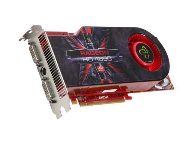
I use 4 monitors on my setup.  The mobo has built in support for two (actually three) graphics cards and onboard video.  I happen to have two Radeon 4890 video cards I could install for crossfire for the other two monitors.  They are getting kind of old, use a lot of juice, but I've always liked them.   One was in the previous machine, and the other is was pulled from my son's machine when he wanted an HDMI output with sound for watching streaming video and tossed the card back to me.  They only have DVI outputs.  I may swap something more modern later but have these for now.   Later I decided to bail on crossfire due to the power required and their are reports the 4000 series would choke on multiple monitors in crossfire.

XFX Radeon HD 4890 HD-489A-ZDFC Video Card

---------------------------------------------------------------------------------------------------------

COOLER MASTER Hyper 212 EVO RR-212E-20PK-R2 Continuous Direct Contact 120mm Sleeve CPU Cooler Compatible with latest Intel 2011/1366/1155 and AMD FM1/FM2/AM3+

Spent another $29 on a fan I didn't really need.   I was planning on using the stock fan that comes with the processor, but my CPU is taking too long to come and meanwhile I read too many reviews.  Plus Newegg sent me a promo code.


Finally!  The 4770K processor came.   There was a problem with the order at the Intel Employee store, then it had to come cross country by snail.
Photo


Popped open the socket by unhooking and lifting the clamp wire


I had a little trouble with the fan's backplate.   The case has a handy hole on the back panel so you can access the back of the processor.  Only problem is that two of the holes are misaligned and are hidden beneath the metal.   A little jiggering and holding nuts with needlenose pliers I was able to get the bolts in.


I was a little unhappy when i flipped it back over.  The mounting posts are on top of some of the DDR traces, and during bolting in there were some scrapes on the board where the posts turned.  Hopefully the DDR traces are not disturbed or shorted.   There may be some impedance mismatch with the bolt on top, I'll have to wait and see if I have memory issues.


The X piece fits over the fan heat plate and screws in.  Not too tricky once you figure out how it is supposed to go.
Photo

Snap the fan on the side of the heat sink.  What a monster.
Photo

Wow.   This is one of the most crowded cases I've had.  Not sure why it is so tight, the case itself must be on the small side.


Wired and checked connections, plugged in monitor, keyboard and power.  Pushed the button.  Dead.  Cold.   Dead.  Pushed the button on the board.  Dead.  Fail.

After I unplugged everything I saw the problem.  Stupid stupid stupid.   In this case the power supply is on the bottom.  I like that design, it is in a much better place.  However that means it is upside down and the power switch is upside down.  I had it turned off.    Ha ha ha.

Wired it back up and w00000t!!!!   It boots to the ASROCK screen.  3.5G i7 3770K is reported, with all 16Gb of memory.  Sweet.
CPU temp is 38C.  Set fans to performance mode.

Problem with the DVD drive.  Detected it but wouldn't boot from it.   Strange.  Replaced the SATA cable.  Got stuck again saying to insert boot media.  I"m using a Win7 upgrade DVD which I'm pretty sure I cold booted from on my last build.  But it ain't happening.  I do remember in the past I always bought IDE DVD drives because I've never had good luck booting from SATA.  That is no longer an option, there is no IDE support.

Just for laughs I put in an old Ubuntu live CD.  8.06.  Ancient.  Same result, won't boot, says Select proper boot device.

Tried an old ubuntu boot thumb drive.  Boot error.  Arrggh.

Tried putting in the DVD that came with the mobo.   Can't boot.  Can't read.

http://www.tomshardware.com/forum/250291-32-booting-sata-drive
I guess this is an old problem.  May not be my drive.  This is an old copy of windows and it doesn't like SATA drives for booting.

I hate to do it, but I may try to boot from the old hard disk, just to get going.
Plugged in the menagerie of old SATA drives.  I have one IDE disk that I'm planning to use via an adapter once things get going.

At least now it seems I can boot Windows 8 from my old hard drive.  I still want to drop back to windows 7 and load it on the SSD.  But I need to make this box do something useful.   I have the desktop!
I had to re-register windows over the phone.

Can't seem to get the network running.  Running the mobo DVD to see if I need drivers.
Now I learn I had the mobo DVD in upside down.  Idiot.  Now that windows is up, the DVD drive works fine.  Installed all drivers off the DVD.   Manually had to install LAN drivers to get the internet working.

Can't see the built in Intel graphics at all.  Seems like a driver must be missing.  Two of four monitors aren't coming up.

Windows experience index for the processor is 8.1.  Seems like it should be higher, but I haven't OC'd yet.  4890 gets only a 7.5.   The old disk drives are dragging down to 5.9 and the system seems slow as a pig.  A fairly in shape pig, but not what I wanted.  I need to figure out how to get the OS moved to the new SSD and get the garbage cleaned out.

Looks like I"m bogged down with drivers installing, each one taking half an hour then forcing a reboot.  In the background the backup software is running, etc.

After getting the machine running with Windows 8, I tried again to install windows from my CD onto the SSD from within the OS.   This should have worked.  However the drive spun and never identified the disk. Whaaa?  I opened the drive and looked at the disk.  Big smear on it.  Cleaned it and put it back in.  It works now.   I pulled the old hard drives and tried a fresh boot and now it works!!!!   OK the whole problem with the Sata DVD drive was only that the disk was dirty, and the other disk was in upside down.  Unbelievable. There is no problem booting from a SATA DVD drive for a fresh install. Geeez.

I loaded windows 7 on the SSD successfully and went through all the updates.  I needed to load all the drivers from the mobo CD to get the internet LAN working at all.  That took a zillion reboots and hours, but no major issues.

The built in Intel graphics aren't working.   The device manager doesn't even see them.  A little poking yeilds an unpleasant result.
http://www.intel.com/support/graphics/sb/CS-031040.htm#8
Can I install an external PCI Express* graphics card and use it in parallel with Intel graphics? 
No, Intel graphics cannot be used along with an external PCI Express graphics controller. Installing a PCI Express graphics controller will disable Intel graphics.

Ouch!  I can't do what I wanted and drive two monitors from the mobo and two from a PCIe card.  I'm going to have to install the second 4890 card or my little 5450 PCIe x1 card to get the other two monitors.  Too bad.
I tucked the other Radeon 4890 card into the mobo after all.   Wow this build is insane.  I also put a spare case fan on the case cover because I started to worry about the heat.


A slight issue is that the second Radeon 4890 has a case fan glommed on the side because it's real fan died.   That fan is extending over and blocking one of the USB3 headers.  Until I fix that, two of the USB3 on the front panel won't be operational.

Rebooted and now all four monitors come up.  Hooray!

The SSD windows experience index is only 5.9.   No better than the old drive.  I think I need to try it in another SATA mobo slot and make sure I have a SATA3 cable on it.  
I found a couple tweaker pages that helped

Simply moving the SSD to the Intel SATA port on the mobo improved things from 5.9 to 7.9.  Whew.   Now my poor 4890 graphics card is bringing up the rear.  Strange in windows 8, the processor was an 8.1.  Now it is only 7.8.  But I haven't OC'd it at all yet.

Put the video cards into crossfire, no appreciable difference.  Graphics is the lowest number with two Radeon 4890s in crossfire.


CPU-Z results below