Search This Blog

Sunday, June 26, 2011

Night Vision Goggles, built from the junk bin

This project is an attempt to build night vision goggles for next to nothing.  A little nuts, but I'm here to have fun!

I've been experimenting a lot lately with IR LEDs and found that I can get a lot of intensity out of them.  This could be used for creating some home brew night vision goggle solutions.

They do sell commercial IR illuminators for night vision, so this isn't an entirely new idea.  They come for a variety of prices.  Search for "IR illuminators", here are some examples.


But the LED diodes are not expensive.
They sell ones with very wide and very narrow illumination patterns.  Here are some I bought recently from Digikey.  10 for $3-$5.


11067-1001-NDDIODE IR EMITTER 5MM IR CLR LENS00.48500$4.85
210475-2871-NDEMITTER IR 850NM 5MM RADIAL00.48400$4.84
310475-1458-NDEMITTER IR GAAS 950NM 5MM RADIAL00.31300$3.1
Links
http://search.digikey.com/scripts/DkSearch/dksus.dll?Detail&name=475-1458-ND
http://search.digikey.com/scripts/DkSearch/dksus.dll?Cat=524328&k=67-1001-ND


Now you could spend 200+ on one of these snazzy things....


Or you could build an illuminator by modifying an LED flashlight, I'm sure you already have a dozen around the house.  This one has a nice housing, a lens, and supports a cluster of LEDs.   


And use a camera and display from your pile of used cell phones (I hope everyone has such a pile).  An older one with a smaller display would be best.
Now the crazy part is mounting  the cell phone in a headset and sealing up the light output to your eye.  A pair of drugstore magnifying glasses will allow you to put the display close to your eye.  I happen to have one of these phones that is out of service when I got a smartphone.  I has a 3Mpixel camera and a built in display on the other side.  95% of the vision system i need.

File:LGDare2000ppx2Rotated.jpg

Although the old clamshell phones would work too.  Maybe better because the display is smaller.  I've got some of these too so I'll see what works best.


This project is underway... so the post will build as I complete it.

Saturday, June 11, 2011

Improved High Power IR LED speed/red light camera photo blocker


Last time I built the blocker you see in the photo, see my previous post. http://blog.workingsi.com/2011/05/ir-led-speedred-light-photo-blocker.html.   I'm playing with technology to ruin the plate photo taken by speed and red light cameras.  This would also apply to automated police license plate screeners, toll collectors like EZPASS, etc.  Last time I learned a lot and made some mistakes, so I'm amping it up a bit to try to make a more effective design.  I won't repeat the backstory in the other post.  This post I'm going to take a more scientific approach and pull out all the stops.

This is just for fun and education and I have no intention that I or anyone else will use this for inappropriate purposes.  This is just a playground for technology.

Last time I focused on making a plate out of cheap components that was easy for anyone to build.  I used a cheap plastic license plate frame and TV IR diodes.  The end result looked totally innocuous and was fairly effective in messing up photos taken in lower light, but not so great in broad daylight. 

Now I'm going to try to take this to the next level.  This high power LED is $12, but is 10X more powerful and has a wider field of view than the TV remote IR diodes.  


One downside I noticed when I got the parts, is that it appears  the LEDs are not sealed up.  There is no lens on the top of the LED, so for the road, they would need some sort of lens or cover.  A problem for later.

Another choice is on ebay from overseas sellers.  Twice the power, but still looking for real data sheet and it seems kind of fishy and over rated.  It may be the same component.

These diodes run at 1A instead of 100mA, and can handle surges up to 5A .  With 100mA I had plenty of trouble last time keeping the power in each component in it's rated range using a resistor as a current limit.    I was dropping 3V at 100mA  in the resistors, so with 300mW the 1/2W resistors still get pretty hot.  I did learn that it is most efficient to put multiple LEDs in series.  Last time I put chains of 6 together, which was 1.5V * 6 = 9V, and the remaining 3V dropped across a 30ohm resistor.   That won't work well at 1A, I'd need a 3 ohm resistor and I'd need resistors rated for 3W!  These are small enough that I could mount an array of 4 or 8 of them without drawing any attention.  Also the high power LEDs have a slightly higher forward voltage, so I can't put as many in series.

Generally people drive these big high power LEDs with switching circuits.  I can dump 5A peak through these and switch it on and off with a duty cycle of 20% and keep the steady state average to 1A.  It is a lot easier to control pulse width than it is to build a constant current source at 1A.   That would require an amplifier to regulate with feedback and lots of high current parts.  I need to keep the frequency of switching in the >10kHz range to make sure the diode is on longer than the frame time of the camera so I'm certain it appears on in the picture, especially when it is bright out.

The other thing I learned is that heat is a big problem, and at 1A it is going to get very hot.  So this time I will use a nice blank metal license plate frame that will act as the heat sink.  The license plate will also be part of the heat radiator.   Generally I'm going to be dissipating 1A * 2V * 4 LEDs = 8W per string, with two strings this is as much power as a LED light bulb for your home, and those get really hot.

I need a good metal license plate frame.   I was planning on using black like this one, when I had black plastic IR LEDs.


Now my LEDs are white.  I think that chrome would make it harder to see the LEDs.  I'm also going to try this one:


One with a logo might add some visual distraction, but I'm not sure if the holes will mess up the logo


I'm going to drill out holes for the LEDs to shine through, and possibly mount a power switching transistor onto the metal frame as well.


This is the initial test circuit I will use to start powering the LEDs.   The idea is to keep an average 1A current flowing through the LEDs, while powering from the 12V automobile power.  Since limiting the current with a resistor would be the same as making a cigarette lighter (way too much power and heat from the resistor), I'm using duty cycle as the means of regulating.  The LEDs can handle 1A average, but 5A peak.  So i'm setting up the LEDs via the forward voltage to pull 5A.  The 1N4002 are simple rectifier diodes that are used to drop 1.25V each at 5A.  They are also rated for 1A constant.  I could have put in at least 1-2 more LEDs but they were too expensive.

I'm just using an Arduino during prototyping to create a variable width 5V pulse that I can control easily.
Arduino Duemilanove Board  This is a simple programmable microcontroller that anybody could use.   Buy it and plug it into your USB, load the free software and send the program.    Eventually this could be a hardwired oscillator.    The FQP50N06L is a huge switching transistor that is driven by a 5V input swing and has <0.05 ohms on resistance.  It can handle 52A at 60V.

Some other possible solutions are commercial PMIC - LED Drivers, there are standard auto LED drivers like these:
I'll keep looking, I haven't found a part yet that I like, so i'm sticking with my circuit.  I'm going to have to solder up the LEDs to even get started, as they are surface mount.   Here is the embarrassing kludge of the Arduino breadboarded to the NMOS switch, 1N4002 diodes and wired to the four LEDs soldered to a vectorboard.  I also put in a visible red LED in parallel just so I could see when it was on.  This jig was just so I could make sure the LEDs were working before I went on.  I also added a 2K resistor pull down to Arduino pin 11 to keep the power off to the LED when the Arduino is booting.


Zowie!  That is bright looking through the camera!  Haven't adjusted the power yet, no idea if this is max. Components do get a bit warm.   I did notice like the other 850nm diodes, they glow a faint red when turned on.  This caused me to discard the last set, but I have since learned that nobody will see a faint light outside.


This is the Arduino program that toggles pin 11 to power the LED.  Nothing to it, just a blink program.


void setup() {            
  // initialize the digital pin as an output.
  pinMode(11, OUTPUT);
  digitalWrite(11, LOW);    // set the LED off
}
void loop() {
    digitalWrite(11, HIGH);   // set the LED on
    delayMicroseconds(20);              // wait for a second
    digitalWrite(11, LOW);    // set the LED off
    delayMicroseconds(80);              // wait for a second
}


Had to update the schematic.  Learned that when the Arduino is off and booting up or loading a program, the outputs float and the LED string turns on hard, sending way too much current through.  Fixed this with a pulldown resistor:

I also found that when I flash the LEDs at a slow rate, when I try to take a picture the automatic exposure control of the camera gets really screwed up.  That is a good thing!  I don't know if the speed cameras have automatic exposure control, I assume they do, and how much in advance of the picture they set the exposure.  Normally exposure control is a sensor running and integrating the scene over a long time.  Long time here means ten milliseconds up to a second.   What I want to happen is to trick the camera into not seeing the light, and then blinding it when the picture is taken.  Now that gets me back to trying to detect the camera flash, which is just not going to happen  at a distance in an outdoor environment.

As I calculated before, a speed camera is going to have a pretty short exposure to catch a moving car without blur.   An idea I will explore is constantly ramping the brightness up and down at a high rate, or having multiple banks that flash and ramp brightness.  At least one bank must be on all the time to be sure the camera doesn't take the picture at the wrong moment.  On second thought, there is some possibility that might work as well, by tricking the camera into thinking the scene is bright, and then make it underexpose the picture.  Seems a little shaky, will require testing.

Next I need to add a way to monitor the current, the Arduino could do that by measuring the voltage somewhere in the string, that is what the commercial drivers do.  Either that or I pick up some of the commercial LED drivers, and maybe some more LEDs  :-)

Decided that speed camera vendors must sell their wares too, and provide data sheets  to money hungry municipalities.  A little google work found one!   Turns out it can use an INFRARED flash.   So that explains why I can't see the flash.  It also confirms that an Infrared LED will not be filtered and should be effective.
http://www.gatsometer.com/files/file/brochures/high-res/en/leaflet_RS-GS11_ENG.pdf
Answers some critical questions.  1/1000 shutter speed, 0.3sec to get the exposure right, 12bit dynamic range and a CCD sensor (CCDs are sensitive to bloom, meaning flooding of light across the sensor when it is too bright).

Now I have enough information to do some math with some wild guesses to see if there is any hope.
http://www.mathsisfun.com/geometry/steradian.html   has some W/sr equations.
http://www.gizmology.net/LEDs.htm  has a lot of good equations on radiant energy
http://www.iala-aism.org/chapo/publications/documentspdf/doc_229_eng.pdf  has information on measuring lights

No guarantees on this math, but first I need to figure out how much power the license plate reflects from the flash hitting it, knowing the flash power rating above:
Next I figure out how much power the LEDs manage to get into the camera lens:

I'm not totally sure of the flash calculation, still looking up resources on flash intensity.  However the result so far is that the LEDs will be 10X brighter than the light reflected from the flash off the plate.  Not bad.  I think I'm being very generous about how much power makes the return trip, since I'm not accounting for spreading.  Now keep in mind the camera advertises a 12bit dynamic range, which is 2^12 =>4096:1 signal to noise. As a former camera designer, I know that is BS, a camera really has at most a 2^11 usable range, or 2048:1 and that is being generous if the scene and settings of exposure are optimal.  The output ADC may have a 12bit range, but the scene content can not be that large.   You can get maybe 10K electrons in a CCD pixel, and have a noise floor of 100e reading them out.  Any signal down near the noise is not going to be sharp enough to get you a ticket.  The scene will be centered somewhere in the middle if they got the exposure correct, so count on 100:1.  All that said, the camera can still distinguish items in the scene that are 10:1 in brightness easily.   Now a human has to look at the photo, and it is a matter of how much they process the image.
A human can only see about 2^6 or 64:1 dynamic range.  Conclusion.  There is hope that the IR LEDs will be bright enough to mess up the picture.  I could have a lot of errors in my assumptions, but still we are in the ballpark to be effective.

Back to the lab, got some more LEDs in the mail...

Got four more SFH4232 diodes and wired them up with the other four in as tight an array as possible.  Hand soldered the surface mount components, and I'm disgusted with my solder job.  However it should work.  In a final product a small PCB would allow you to pack these closer and make a ground plane for a heat sink.  The diodes have a heat slug on the back that I'm not able to take advantage of.  My plan is to use the metal license plate and frame sandwich to draw out the heat.


Next I have to polish up the Arduino's control program.  I want to flash the LEDs and sense the current back to the Arduino in a control loop.  This is how the commercial LED drivers work to regulate the current.  The power is so high that a few seconds of messing up the code could blow $100 worth of LEDs, so I'm going to test it with some low power indicator LEDs first.  Breadboarded up the Arduino with two FPP50N06L switching transistors.
http://search.digikey.com/scripts/DkSearch/dksus.dll?WT.z_header=search_go&lang=en&site=us&keywords=FQP50N06L-ND%09&x=10&y=15


Needed to boost the PWM frequency of the Arduino to greater than the shutter speed of the camera.  Normally it is about 500KHz, too slow for the 1/1000 => 1KHz shutter.  Stole the code here to bump it up:
http://www.arduino.cc/playground/Code/PwmFrequency

Worked right out of the box, checked it on the scope.  Now the frequency is 3.9KHz and I can just use the analogWrite() function without running a loop as I did above.  That way I can save the brainpower of the Arduino for my control loop.

Add the analogWrite to the LEDs, the analogRead for the sensor, and a serial write.  I'm going to load this and see if this slows down the PWM frequency on the scope.  Still 3.9KHz.  Sweet, the computational overhead is not messing up my flash rate.  This should work.

Got some 5W  1ohm resistors so I could measure the current in the diodes by measuring the voltage drop.
http://search.digikey.com/scripts/DkSearch/dksus.dll?WT.z_header=search_go&lang=en&site=us&keywords=MRA05-1.0-1%25-ND&x=10&y=14
Made sure not to buy wirewound resistors, because they are inductive and since i'm switching the current through them it would ring like mad.

My first measurement of the current was only 0.39V -> 390mA!  I wanted 1A average current.  The forward voltages are not stacking the way I expected.  Ramped up the duty cycle to 40 and got the current to 790mA.
Diode array is getting WICKED HOT!  I'm going to have to mount this on the plate frame and get some heat sink action or I'm never even going to be able to test this thing at full power unless I can get the heat out.

First I have to drill out the license plate frame in a hole pattern that matches my hand kludge diode array.
I will take a full size picture and tape it on, then drill.


I used the black frame as a practice, since my plan is really to use a chrome license plate frame of the same type.  The shiny chrome will disguise the LEDs better than black.   Here are the holes I drilled with the drill press.  Drilling went smoothly, the pot metal license plate frame was easy to drill.  However the metal was shiny under the black and despite my best efforts the paint was marred in a few places.  If I was going to use this as a final project, it would need some touch up paint or to be taped before drilling.


Taped in the light array as a mock up just so I could dissipate the heat and take some photos.  You can see the black electrical tape if you look.  Here is the frame, light array and license plate assembled without turning it on.


Connected to the Arduino and the driver circuits


Powered up to 800mA per diode.  Max is supposed to be 1.0A, so not quite full power.  Frankly I'm not impressed yet.  The previous version seemed to be just as effective at less than half the light power spread over a larger area.  What is going on?  The camera I'm using to photo this is my cell phone.  It does an auto exposure, which I've said above I don't think the traffic cameras have time to do.  It closes down and I get the same picture no matter how bright the light is.

To prove my point, I took a picture of a 100W light bulb on the ceiling.  OK it was really a 23W compact fluorescent 100W equivalent.   You can see the wood grain an inch from the bulb, and this has 4X more power than my LEDs based on input power.   Now the LEDs may be more efficient than fluorescent, but the camera sensitivity is higher to visible.  I should have done this before we went on this ride!

So is the project busted? ... no I don't think so.   It depends a lot on the camera and photo conditions.  As I said earlier, taking a photo of a moving car in outdoor environment and reading the plate is not easy.   It needs a high performance camera that is going to be on the edge of working, so it won't take as much to mess it up as it does the camera in my basement.  First I need to find a camera without automatic exposure.

One way this is quite likely to work , is to actually drill holes in the plate, and put the IR LEDs behind the numbers.  My state has white plates, so it might not be too obvious.   The number behind the LEDS won't be readable, that is for certain.  That is a much easier block than a light near the numbers.  I'll try that next.  Try that idea at your own risk, I'm not telling you it's OK to do this.

Here are some shots of a license plate I found by the side of the road, drilled with four high power LEDs behind it.  Since the plate is white and the LEDs are white they are pretty invisible until you try to take a picture.


Here is the plate at night, taken from a cell phone camera.  The shot is dark because the LEDs make the camera adjust to be very dark.


Monday, June 6, 2011

IR LED speed/red light license plate photo blocker

My town installed two red light cameras and a speed camera in a 1/2 mile stretch into my neighborhood.  They lowered the speed limit too.  The week they put up the speed camera I got three tickets for going 42mph and 43mph in a 30mph zone.   That made me all warm and toasty inside.

So I thought I'd play with technology to spoil the photos of license plates and share the fun with the world.
Can't jam the radar but I could theoretically make it harder to get a photo of my plate.  They want to have really clean photos to stand up in court.

OK - so this is totally for fun and i'm not advocating anyone to break any laws or even bend them.
Whatever you do is totally up to you, I bear no responsibility.  If this is illegal where you live, I encourage you not to try it.   This is a playground for technology and not anything else.  Reading further in this blog is acceptance of the fact we are all responsible for our own actions.

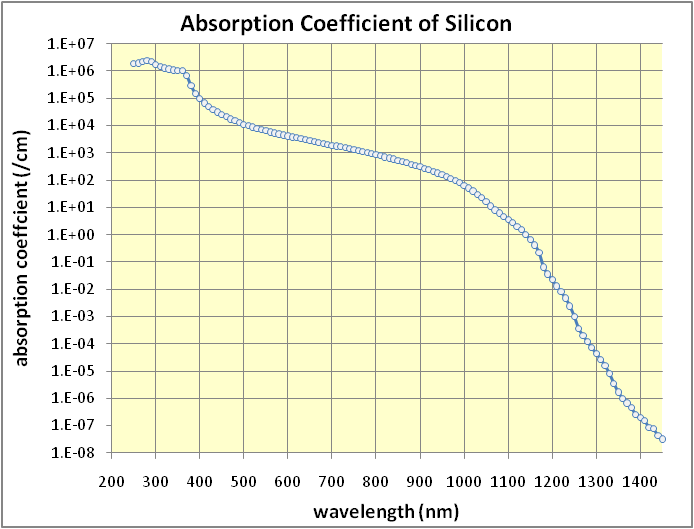
I used to build IR cameras for a living, so I know that all digital cameras are sensitive to
near IR radiation.  IR LEDs transmit on wavelengths from 850nm to 1100nm.  These are what are used
for IR remotes, etc.  Invisible to the eye but visible to silicon digital camera sensors.
Visible light is is 390-750nm.  Silicon is used as sensors, and silicon absorbs these wavelengths.


Absorption coefficient of silicon


Some filters can be applied to cameras to filter out this wavelength, to improve the
sensitivity of the camera to visible.  However sharp filters are almost physically impossible
and very expensive, they require many precisely controlled layers of deposition.
These are also used as invisible illuminators for security cameras, so we know cameras see them.

First I will leave them illuminated all the time, rather than try to catch the flash with a photocell some other nonsense.  That is how photographer's flash extenders work, they sense the flash and make another flash fast enough that the shutter is still open, but the sensor is a lot closer and things are much more controlled than the outside environment.  Speed cameras must have a pretty fast shutter speed (I calculated this below) too.  The reaction time would be short, the flash hard to detect.

There are some phone apps to warn you of these cameras, like this one.  Radardroid Lite
Tried them and they are OK, but it didn't have the same "stickin' it to the man" appeal.

Since IR is invisible, this should be legal.   I can't cover the plate, license plate covers are illegal in my state.  The IR LEDs must be on the edge of the plate, close enough that some of the numbers can't be photographed due to the "bloom".  Just a little glare to make it hard to read and the ticket will be blocked.

I had seen that myth busters tried something like this with visible LEDs and claimed it was busted.  But had it worked they wouldn't be able to show it for legal reasons.  I'll try IR LEDs, and I'm going
to amp it up with a bunch of lights.  The glare will be huge I hope.  Daytime light may be too strong, but
what the heck I'll try it anyway. I'm a bit unsure that the lights will be bright enough and this may all be a boondoggle.

One issue will be heat.  I want to run the diodes at as high a current as possible.  I considered flashing
them at a high rate of speed to cool, but that might miss the exposure all together and the average current
wouldn't be any higher.  So I might as well run them off DC to maximze intensity.

There is a possibility that flashing at a high rate might be better to throw off the exposure control
of the camera.   However I don't want to risk the lights being off during the time the photo is
taken, so the flashing will have to be fast.  I considered flashing them in banks, but that wouldn't
have the effect of messing up exposure control.  I think an all on - all off flash would be most disruptive
to photography.  I will have to experiment with what works best.

Speed cameras must have long focal length lenses and short exposure times to get sharp photos
of moving cars from far away.   That's why they need a flash, they need all the light they can get.
I'm guessing they need exposure times of 1/250 to 1/1000 to capture the moving car.
An electric flash is a very fast burst of light (1/1000 of a second or less, sometimes much less)

Flashing the LEDs at 1kHz would mean that 50% of the time I'd miss being on when the
photo was taken.  IR LEDs are designed to modulate at 30-40kHz for remote control.
So modulating at >5KHz will keep the LEDs on for the photo time and will easily be
in the response time of the LEDs.

So I bought 40 IR LED's from Digikey of various wavelengths.  I sorted for the highest
power with reasonable field of view, and of course, low cost!!

I already had 10 IR SFH415 U diodes from the IR sleeper and TV bgone projects.
I also bought these others from digikey, all were less than 50 cents apiece.
I wanted a mix of wavelengths but i especially wanted the 850nm ones, because they
will be closer to visible and will put more energy into the camera.  Maybe I should
have bought all 850nm, but I thought a mix for experimented would be best to start.

11067-1001-NDDIODE IR EMITTER 5MM IR CLR LENS00.48500$4.85
210475-2871-NDEMITTER IR 850NM 5MM RADIAL00.48400$4.84
310475-1458-NDEMITTER IR GAAS 950NM 5MM RADIAL00.31300$3.1
Links
http://search.digikey.com/scripts/DkSearch/dksus.dll?Detail&name=475-1458-ND
http://search.digikey.com/scripts/DkSearch/dksus.dll?Cat=524328&k=67-1001-ND
http://search.digikey.com/scripts/DkSearch/dksus.dll?WT.z_header=search_go&lang=en&site=us&keywords=475-2871-ND&x=9&y=15
http://search.digikey.com/scripts/DkSearch/dksus.dll?WT.z_header=search_go&lang=en&site=us&keywords=475-1458-ND&x=9&y=14

As you can see, they didn't break the bank!  So far I've spend <$20.  The traffic tickets were $40 each.


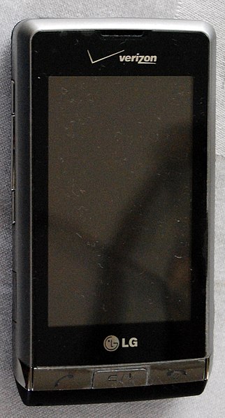
Here is a sample of what they do to a digital camera when illuminated!
I can't show you what they look like to my eye, but they look dark and off.

I'm going to experiment with illumination, photos and placement when the parts come.

Got a license plate frame, plan is to drill it out and insert the LEDs.  Got black to
make them less obvious.  Got one that had a wide border along the bottom that will
be close to the numbers.  This one has a cheezy "carbon fiber look"  that has a
shiny woven look that will disguise the LEDs a little better.  It is thick plastic and
hopefully will drill.  Here is a photo with it on an old license plate


Pilot Automotive WL-714-CF Carbon Fiber Look Car License Plate Frame

http://www.amazon.com/gp/product/B002VKO60C/ref=as_li_qf_sp_asin_il_tl?ie=UTF8&tag=workingsilico-20&linkCode=as2&camp=1789&creative=9325&creativeASIN=B002VKO60C


This was the results of my initial comparisons between the three LED types
IR LED                        wavelength                      comment                        brightness
OED-EL-1L2                     950             clear lens, high view angle              Highest
SFH 4556                          850              glows dull red to the eye               Medium
SFH 415 U                         950              dark and innocuous looking          Medium

Generally, the clear LED was brightest to the digital camera, and the 850nm diode
which should have had a wavelength advantage, wasn't appreciably brighter.
Worse yet, it had some visible wavelength dull red glow.  Not bright, but
it would be visible in the dark and raise suspicion.  Too bad the clear LEDs are
a little more obvious but seem to be the best.


In this photo the LEDs are in order left to right, SFH 4556, SFH 415 U, OED-EL-1L2, SFH 415 U.
You can see the OED-EL-1L2 is the brightest (third from left).  The 850nm diode has no
particular brightness advantage over the 950, which surprised me since it should have several
times the absorption by the camera.  It's visible glow is probably going to kill the use of this one.

OK, for the OED-EL-1L2, the peak current is 1A, but the power dissapation is only 150mW
and the DC current allowed is 100mA.  The forward voltage is 1.2 to 1.6V
http://www.lumex.com/specs/OED-EL-1L2.pdf

That means that I want to shoot for 150mW to put the LEDs at their max light output.
100mA DC times 1.2-1.6V Vforward = 120mW to 160mW.  So I have to keep the average
current to 100mA.   My prototype will power the LEDs from 5V Arduino output but later
I may make a 12V simple circuit to do the oscillation.   5V/100mA is 50 ohms.  But since
I'm flashing at 50% duty cycle, I will need 25 ohm resistor in series.   The above photo was
takin with 100ohms, so I will be twice as bright as that.

Obviously the Arduino can flash an LED at that kind of current.  The TV bgone uses a 2n3904
bipolar to switch the current, without any series resistor.   I also have a pile of 2n7000 mosfets
that will save me some resistors.  They can take 350mA.  This was the tv bgone circuit.  As
you can see it needed two stages to fan out the current drive.  the 2N7000 won't need that
as the gate draws no current.  Everyone should buy a bag of these, for 0.17 for 100.

To avoid a series resistor, I could drive the LED with a low duty cycle high current pulse.
The 2N7000 has a Rds(on) of about 2 ohms at 0.5A.
http://www.st.com/internet/com/TECHNICAL_RESOURCES/TECHNICAL_LITERATURE/DATASHEET/CD00005134.pdf
The LEDs could handle 1 amp peak (remember from above).   5V - 1.5V (Vforward) = 3.5V across the transistor.  3.5V/2 ohms = 1.75A.  Too high for the LED without any series resistance. But if I put two LEDs in parallel, I will split that current and be at 0.875A per LED.  This is not a perfect solution because the
LEDs may have slightly different forward voltages, and will not share the current equally.  But best I can do.

Now I have to keep the LEDs from dissipating more than 150mW on average.
0.875A * 1.5V = 1.31 W peak.   150mW/1.31W =11.5% duty cycle.

SoI could flash LEDs at 10kHz, with 11.5% duty cycle, two LEDs per 2N7000 transistor, no series resistors.   5V supply.

To save components, I could bring the duty cycle up to 50%, and load on more LEDs in parallel.
I could put 10 LEDs on at 50% duty cycle, 0.50 * 1.75A * 1.5V / 10 = 131mW per LED.

I'm in trouble on the 2N7000s.  they only want 1.4A peak current, and I'm doing 1.75A.
Thought I'd run it anyway, if I blow one they are cheap.  However it gets scary hot and the
LEDs don't at all.  I think I will switch out the 2N7000 with a FQP50N06L monster.
These cost a over a buck a piece but they are 50A rated.
Problem is they have a really low Rds(on) = 0.2 ohms.  So my current calculations are
out the window and i need to introduce a 2 ohm resistor.  Arrgh.

OK.  Rethink time.  Is flashing really better than DC?  Time to experiment because flashing
is going to take many more components.  DC will take a couple resistors, while flashing will
require an oscillator, switching transistor, etc. 

I set up an experiment flashed, side by side with DC.   The flashed had 50% duty cycle with
half the series resistance.  100ohms for flashed, 200 ohms for DC.  The DC was noticeably 
brighter to the camera.  OK. DC wins for complexity and effectiveness.  

The lower 5  LEDs are the DC, the upper 5 are switched at 10KHz.

I mocked up an array of LEDs and resistors and plugged it into 12V for one last full
scale test before building up the license plate final version, and got a surprise.


While this was on, it started to smell hot.   The resistors were getting really warm.  Doh! I have 1/2W 100 ohm resistors, so that I put (12V-1.5V)/100ohms=105mA through the LEDs, their max rating.  However since I'm running from the 12V auto supply directly,  that puts 10.5V * 1.5mA = 1.1W through the resistors.  Before I had been running off 5V during tests and the resistors did not get so hot.  This simpleton project is becoming more complicated because I'm trying to make a cheap solution.

OK, brain finally started functioning.   Many LEDs will be in series with a resistor
to set the current, this will prevent dissipating too much power in the resistor
and generally be more efficient, fewer components, all good.
6 LEDs in series like christmas lights, 6*1.5V=9V.   12-9V=3V across the resistor.
100mA*3V=300mW, which is in spec for the 1/2 watt (500mW) resistors.  Might even
be able to squeeze in a 7th LED.    3V/100mA= 30 ohm series resistor.


Tested out strings of 6 LEDs in series with 30 ohms.  Gets nice and bright, doesn't get hot, doesn't waste power. 

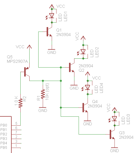
OK, here is the complete circuit drawn up.  Strings of 6 LEDs will be used.


I think I can pack the LEDs in and solder them into chains.  So the big structure at the bottom will look like two rows of alternating staggered LEDs with no interruption in the middle for the ground.

There will be a tight cluster in the bottom center of the plate, and a smaller cluster at each side which is nice and close to the numbers.

Drilled a hole in the license plate frame as a test (see link above) and it drilled pretty well, nice clean hole.
The challenge is going to be making nice neat regularly spaced holes or the whole thing will look amateur.
I put one of the clear IR LEDs that won the brightness test, but it looks really obvious in the frame.  Maybe somebody with a tricked out car might not care, but it really looks like a light, even when it is off.  The solid color SFH 415 U look far better and less suspicious.  I'm going to have to use those, i'd never have the nerve to put the others on the car.  Forget the nice shiny OED-EL-1l2s.

Hard to get a good photo to show what i mean, but here it is...


Obvious Clear LED (shown off, which is how it looks to the eye).  I thought the pattern would hide it.

Nearly invisible black IR LED.  It is a bump of course and the picture isn't great.  But you get the point.

I was planning to use my CNC machine that I've been writing about to drill the holes.  Sorry if not everyone who reads these happens to have one.   However the CNC machine stage is small enough I'd have to do the job in three passes, and I got impatient with the setup and just did it on the drill press.  I clamped a bar to the press stage to make all the holes even distance from the edge of the frame, but freehanded the spacing.  I was eager to move this project along and get to some outside trials.   I did OK but not great in spacing the holes and kinda goofed on getting the placement of the arrays even on both sides.  No harm done but a production version would have to be neater.  The plastic license plate frame drilled nicely though, it was a good choice for the project.


Here is a picture of the holes I drilled.  I put the LEDs in clusters to make hot spots in the photo, rather than in a whole line around the plate.  The thought is that unevenness and tight hot spots will be best to ruin the photo.

Next to glue in the LEDs and wire them up!  A note about LEDs since a few non EEs seem to be reading this post.  LEDs aren't light bulbs.  They have a polarity and must be hooked up the right way or they don't light up.   This is how you tell which way to put them in.  Note that not ever LED follows the long lead convention, but the flat side is a reliable indicator of polarity.


Here is a shot of the LEDs getting glued into the main phaser bank in the middle.  Remember that they are in strings of six, so the pattern of anode and cathode is important to be able to easily solder them into strings.  I will show the pattern later.  This is about the best I've been able to capture the look of the LEDs in the frame. They are hard to see.


Daisy chained LEDs soldered up to 30 ohm resistors.  Glued in the LEDs and bent the leads and soldered them together into chains of six.  Make sure to keep the polarity correct in the chains.  A little messy but this is a prototype. 


Here is the finished main LED array (sorry about the 90 degree photo).    Power is off in this photo so you can see how it looks to the eye


For now I'm wiring these into the license plate light power.  They will only be on when the lights are on.  Using trailer light power taps.  Pico 1560D 18-14 AWG (Blue) Electrical Wiring Hot Line Quick Splice / Tap-In 5 Per Package


OK moment of truth.  Did it work??  Eh maybe....

So a lot depends on the lighting.  Taking a photo of a moving car and reading the license plate is not easy.  A speed camera needs a lot of light, a high speed lens, a short exposure time.  So it shouldn't take much to spoil the photo.    This photo was taken with indoor lighting and no flash.   The picture is very messed up, lots of glare but all in all you can still read the plate if you try.  It might not meet the standard of quality to hold up to get you a ticket though.  Of course you don't want to mess up the photo just enough to have them wonder what you are up to.   You can read my plate here, but eagle eyes will reveal this is just an old expired plate I'm using as a photo model.


This time I used the flash.  The IR LEDs are a nice decorative touch, but pretty much useless.  However I'm 3 feet away shooting a plate that isn't moving.  A real photo won't be this good.  Anybody's TV remote in the neighborhood would be probably be totally jammed :-)

I went out on a fairly sunny day and put it on the car.  Stylin' huh?   All in all I succeeded in making something that is not going to draw any attention under normal circumstances.


Powered it up with a battery charger to start.  This later proved to be a slight issue.  Can you read the plate?  I can.  Is it even on??  It was so bright outside I couldn't see the display on my camera.  This is a tough test.  It was bright and sunny.  The car was not moving of course, but I also didn't have a professional camera.  if you see below, it might be better than this photo showed because of the power supply I was using.


Here is a closeup like what you get in the mail when you run a camera.  Still looks like a FAIL.   The LEDs are pretty but noneffective under these lighting conditions.  Notice something strange happened, which may have reduced the brightness.  The LEDs were powered from a battery charger in this picture, and it has a lousy AC to DC rectifier that is probably flashing the lights at 60Hz.  When there is this much light, the camera is taking an exposure shorter than the time it takes to read out the camera's photo array (I told you I used to design IR digital cameras for a living, trust me).  As a result the picture changes while it is being taken, and the 60Hz is not integrated and the LEDs appear to be on in different patterns every time you take a photo.  That won't happen with the car's DC power, so it might be twice this bright when hooked into the car power.  That is why it looks like some of the LEDs are not working.  But anyhow there is zero glare.


So here is my conclusion for now.   There is hope that this would work when it's dark, rainy, or otherwise non ideal for photo taking.  On a sunny day, drive slowly.   Or make the LEDs spell out a message like "I love the police".   I'm not going to go out and run a camera on purpose, so there is no way to know if this is going to work even on a dark night.

Next.... Ramping it up!

What went wrong?  I had the design parameters turned too far for innocuous, stylish and low cost.  I need to redo the project and focus on brightness and high power and see if I achieve something that works first.
The clear LEDs were 50% brighter in my early tests, but I chickened out from using them.   I went for cheap LEDs and simple circuits.  Since then I've seen light up license plate frames for sale so I think the lights could be more obvious without attracting attention.

I'm starting a new post for the next version, click here: http://blog.workingsi.com/2011/06/improved-high-power-ir-led-speedred.html

Some other notes for other ways to do this project...
Later I saw someone driving down the road with this:
So if you wanted you could buy one of these, already has the power connections, and replace the glowing eyes with 850nm high power LEDs.  This is not my style, but if it is yours it is an easy way to beat the camera.  The 850nm LEDs would glow and look like it did before, and be totally undetectable.  Not enough room for all the LEDs I'm using, but could give you a little help.

A little googling found this too.  So this could serve as a starting point for a mod, replacing the LEDs with IRLEDs and keeping low profile.

You could also get one of these, and ramp up the power.  This alone has 140 LEDs, but I don't know what type so there is no way to know if you could achieve enough brightness.