Before I could try out my home brew OBDII interface, the check engine light came on for my 1997 Honda Accord. It has 180,000 miles on it. It is my extra car that I only drive a couple times a week.
I read code PO135, the book says the sensor heater error. Makes no sense. Went online and found this.
http://www.obd-codes.com/p0135
Looks like I need a new oxygen sensor. I reset the code to see if it comes back. No sense in moving too fast, if it is really broken it will set the code again! Might be a fluke.
Currently waiting to see if the code appears again.....
2 days and counting and it hasn't come back. Maybe it was a false alarm
Nope. A day later the check engine light is back. Off to find an oxygen sensor!
Sorry to say i paid my mechanic friend to fix this for me. Work was crazy and i just didn't have time. $300. I am ashamed. ;-)
Sunday, October 31, 2010
Friday, October 22, 2010
Research on the Arduino OBD II interface for reading codes, auto MPG, etc.
This post is just a place to keep some notes and links while I develop this project.
Why do this? Monitor live engine, MPG, etc. Diagnose check engine lights, log data on the car.
I'm also thinking the car modders would love to have lights that respond to what the vehicle is doing, flames that brighten when the engine revs etc.
The project involves interfacing the car's computer, which runs at 12V. Arduino runs at 5V. After that, it is all software.

OK, the ratios of his resistors THEORETICALLY keep the Arduino from seeing 12V, but being a consumer device circuit designer this circuit is not safe. If the K line ever touches 12V, or if one side or the other of this circuit is not powered, RXD will float to 12V and cook the Arduino.
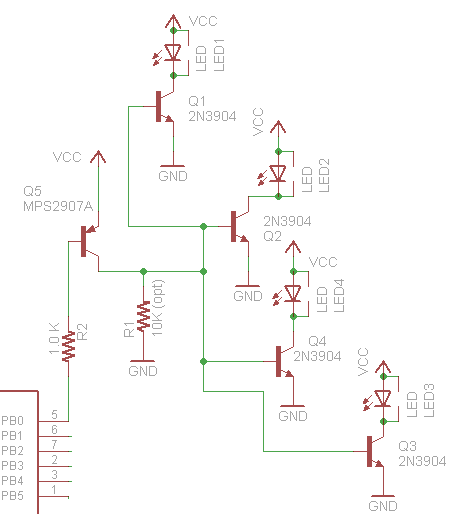
Here is my circuit to replace the MC33290 with a few cheap discrete transistors

NOTE/UPDATE - RX comes from the collector not the grounded emitter on Q4. Schematic is wrong but I no longer have the orginal to edit. This is the way it should be. Somebody pointed this out years ago but for some reason I couldn't see the obvious.

Wikipedia is always my friend. OBDII is a bit more complicated. Different cars use different protocols. Dang. I have Hondas, a 1997 and a 2007. So I'm guessing i can still use the K-line.
This seems pretty straight forward. And i think others have already written the code for the Arduino to emulate this
This guy has some good info on the codes, but I think his circuits have issues and may send 12V back to the Arduino under certain cases. Ouch. I'll fix that. http://prj.perquin.com/obdii/
Still looking at protocols. Found a nice document at
Why do this? Monitor live engine, MPG, etc. Diagnose check engine lights, log data on the car.
I'm also thinking the car modders would love to have lights that respond to what the vehicle is doing, flames that brighten when the engine revs etc.
I ordered an OBD II interface cable from Amazon. No way around this one for $10.95+ship
OBDII Cable, J1962M to Open End, 10ft (144505)
There are some adapter cables to RS232, but why add money buying different connectors. I suppose I could have scrounged a 9 pin from an old motherboard. Too much work. Here is the pinout. This cable has an open wire end i can just solder in.

You can also use a OBDII to DB9 cable, seems like the pinout is standard
http://www.elec-intro.com/obd-connector

Sparkfun has this cable
http://www.sparkfun.com/commerce/product_info.php?products_id=10087
You can also use a OBDII to DB9 cable, seems like the pinout is standard
http://www.elec-intro.com/obd-connector
Sparkfun has this cable
http://www.sparkfun.com/commerce/product_info.php?products_id=10087
OBDII to DB9 Cable
sku: CBL-10087
Here is the basic pinout (OBDII > DB9 Female)
| Pin Description | OBDII | DB9 |
| J1850 BUS+ | 2 | 7 |
| Chassis Ground | 4 | 2 |
| Signal Ground | 5 | 1 |
| CAN High J-2284 | 6 | 3 |
| ISO 9141-2 K Line | 7 | 4 |
| J1850 BUS- | 10 | 6 |
| CAN Low J-2284 | 14 | 5 |
| ISO 9141-2 L Line | 15 | 8 |
| Battery Power | 16 | 9 |
SAE J1962 defines the pinout of the connector as:
- Manufacturer discretion. GM: J2411 GMLAN/SWC/Single-Wire CAN.
- Bus positive Line of SAE-J1850 PWM and SAE-1850 VPW
- Ford DCL(+) Argentina, Brazil (pre OBD-II) 1997-2000, Usa, Europe, etc. Chrysler CCD Bus(+)
- Chassis ground
- Signal ground
- CAN high (ISO 15765-4 and SAE-J2284)
- K line of ISO 9141-2 and ISO 14230-4
- -
- -
- Bus negative Line of SAE-J1850 PWM only (not SAE-1850 VPW)
- Ford DCL(-) Argentina, Brazil (pre OBD-II) 1997-2000, Usa, Europe, etc. Chrysler CCD Bus(-)
- -
- -
- CAN low (ISO 15765-4 and SAE-J2284)
- L line of ISO 9141-2 and ISO 14230-4
- Battery voltage
On 1996 and later vehicles, you can tell which protocol is used by examining the OBD II connector:
J1850 VPW--The connector should have metallic contacts in pins 2, 4, 5, and 16, but not 10.
ISO 9141-2--The connector should have metallic contacts in pins 4, 5, 7, 15, and 16.
J1850 PWM--The connector should have metallic contacts in pins 2, 4, 5, 10, and 16.
ISO 9141-2--The connector should have metallic contacts in pins 4, 5, 7, 15, and 16.
J1850 PWM--The connector should have metallic contacts in pins 2, 4, 5, 10, and 16.
The project involves interfacing the car's computer, which runs at 12V. Arduino runs at 5V. After that, it is all software.
The OBD II has a line called ISO K line, which is a bidirectional serial bus.
It seems there are a couple routes people have gone.
- Using an ELM 323 or 327 OBD to RS232 adapter IC. These are $14 on scantool.net, in clearance. Otherwise they are $30 and seem to be hard to buy right now.
- Connecting direct to OBD protocol, using a level shifter.
- Using a MC33290 or MCZ33290EF level translator IC. Found these are hard to get, end of life'd. There may be replacements, but this is not worth the effort.
- Just use some transistors to build one! I have some 2N3904 that cost 33 cents lying around. This guy did it this way. I think this circuit is missing a resistor for the 12 to 5V division, and the first stage should be to 5V to keep the Arduino safe. But it shows the concept. Easy. Cheap. You can see where this is going. Don't be scared of a couple of transistors!
http://prj.perquin.com/obdii/obdii_avr.gif
OK, the ratios of his resistors THEORETICALLY keep the Arduino from seeing 12V, but being a consumer device circuit designer this circuit is not safe. If the K line ever touches 12V, or if one side or the other of this circuit is not powered, RXD will float to 12V and cook the Arduino.
Here is my circuit to replace the MC33290 with a few cheap discrete transistors

NOTE/UPDATE - RX comes from the collector not the grounded emitter on Q4. Schematic is wrong but I no longer have the orginal to edit. This is the way it should be. Somebody pointed this out years ago but for some reason I couldn't see the obvious.
Wikipedia is always my friend. OBDII is a bit more complicated. Different cars use different protocols. Dang. I have Hondas, a 1997 and a 2007. So I'm guessing i can still use the K-line.
This seems pretty straight forward. And i think others have already written the code for the Arduino to emulate this
- ISO 9141-2. This protocol has an asynchronous serial data rate of 10.4 kBaud. It is somewhat similar to RS-232, but that the signal levels are different, and that communications happens on a single, bidirectional line without extra handshake signals. ISO 9141-2 is primarily used in Chrysler, European, and Asian vehicles.
- pin 7: K-line
- pin 15: L-line (optional)
- UART signaling (though not RS-232 voltage levels)
- K-line idles high
- High voltage is Vbatt
- Message length is restricted to 12 bytes, including CRC
This guy has some good info on the codes, but I think his circuits have issues and may send 12V back to the Arduino under certain cases. Ouch. I'll fix that. http://prj.perquin.com/obdii/
Still looking at protocols. Found a nice document at
http://www.esatinc.ca/News_Letters/OBD_II_Specifications_and_Connections.pdf
It looks like CAN bus will be required on all new vehicles by 2008. I probably have a K wire interface on my older car, but it would be nice to build something that has more generic usage. Also diagnostics may only be on CAN in some vehicles. From this doc
It looks like CAN bus will be required on all new vehicles by 2008. I probably have a K wire interface on my older car, but it would be nice to build something that has more generic usage. Also diagnostics may only be on CAN in some vehicles. From this doc
A simple check to see if the CAN bus is in use in a vehicle, and accessible via the OBD socket, is to connect a resistance meter across pin 6 and pin 14. Due to the combined resistance of the two termination resistors at 120 Ohms each the overall resistance should be read as 60 Ohms. (refer to vehicle specifications)
The CAN bus speed may be as fast as 1 MHz, although the OBD-II ISO 15765 specification specifies two speeds which may be used for on-board diagnostics, 250 KHz and 500 KHz.
So it looks like I should support K wire and CAN both.
Cool - a high paydirt google hit give me this. All the electrical stuff is here!
http://www.interfacebus.com/Design_Connector_CAN.html


Most of the CAN IC's have a uController built in, and cost $20+. Yuck. I could handwire a circuit.
Found these parts that might help. for <$5
http://search.digikey.com/scripts/DkSearch/dksus.dll?Cat=2556697&k=MCP2510
This part is probably worth the $5. The CAN bus was going to max out the Arduino and make it hard for it to do anything else. I would have spent $5 on the devices to interface.
http://ww1.microchip.com/downloads/en/DeviceDoc/21291F.pdf
Uh oh! Looks like I need another part to actually interface to the bus. Boo!
http://archive.electronicdesign.com/files/29/4057/figure_01.gif
http://electronicdesign.com/article/communications/build-a-simple-and-inexpensive-controller-area-net.aspx
This guy has already done it, wants to sell for 30GBP. Yikes. I'm thinking a $10 shield will make a nice project.
http://www.skpang.co.uk/catalog/product_info.php?cPath=140_142&products_id=706
Not so bad, the CAN interface chip is only $1.12!
http://search.digikey.com/scripts/DkSearch/dksus.dll?Detail&name=MCP2551-I/P-ND
And there is a cheaper version of the controller: MCP2515-I/P-ND for $1.98! This might be a <$10 board yet!
OK, ordered the MCP2515 and MCP2551 and got them almost immediatly from Digikey. I put together a quick lash up. Then I finally got around to taking the OBDII cable out to the car and checking if I have a CAN bus. I have a 2007 Accord, and some older cars. I was sure the 2007 would have a CAN bus, since they are required in 2008. But you can guess. Nope, open circuit between 6 and 14. Doh! Major setback and I"m going to go back and build the K line version first now.
A thread with info on another person's project
http://ecomodder.com/forum/showthread.php/obd-mpguino-gauge-2702-27.html
So I have my interface circuit together, using 4 transistors, some resistors, diode and a cap. Made a version for less than $5, not including the prototype board. I will write it up once I'm sure it's really working. Need to get some basic code going to begin talking.
Looks like the obduino32K has some good code. These guys have gone way over the top on the code.
http://opengauge.googlecode.com/svn/trunk/obduino32K/obduino32K.pde
Decided to put my OBDII K line interface circuit together with an LCD and load the obduino32K code.
The code compiled without much trouble, and the LCD comes on, and the K line gets wiggled. Today I will plug it into my car and see what happens. See the circuit diagram above. Basically I am building the circuit from http://code.google.com/p/opengauge/wiki/OBDuinoDiagram but I am not using the MC33290, since I couldn't find one. I put together a level translator with a handful of cheap transistors, similar to the diagrams I quoted above. Functionally equivalent to this picture: Also odd that there are no pull up resistors on the switches.

OK - debug time. The board comes up, the K line wiggles. I tried this in two Honda's and a Toyota and never get past the initial sync. I need to strip down this code to a basic sync and a dump of the response to see if the car is responding and I'm missing or mangling it, or if there is no response. I looked at the data sheet of the MC33290 and I'm pretty sure my circuit should work. I have an LED on the K line (not directly) so I can see there is activity.
Still stuck. I can't get the car to respond to the Init. May be i'm using the wrong protocol, my interface circuit may have problems, or my code is no good. I'm going to begin to deconstruct things and start with some basic bit banging the control lines to see what is up.
I posted my tweaked openguage code so i can pick it up from my laptop, and try debugging in the car...
http://www.interfacebus.com/Design_Connector_CAN.html
Most of the CAN IC's have a uController built in, and cost $20+. Yuck. I could handwire a circuit.
Found these parts that might help. for <$5
http://search.digikey.com/scripts/DkSearch/dksus.dll?Cat=2556697&k=MCP2510
This part is probably worth the $5. The CAN bus was going to max out the Arduino and make it hard for it to do anything else. I would have spent $5 on the devices to interface.
http://ww1.microchip.com/downloads/en/DeviceDoc/21291F.pdf
Uh oh! Looks like I need another part to actually interface to the bus. Boo!
http://archive.electronicdesign.com/files/29/4057/figure_01.gif
http://electronicdesign.com/article/communications/build-a-simple-and-inexpensive-controller-area-net.aspx
This guy has already done it, wants to sell for 30GBP. Yikes. I'm thinking a $10 shield will make a nice project.
http://www.skpang.co.uk/catalog/product_info.php?cPath=140_142&products_id=706
Not so bad, the CAN interface chip is only $1.12!
http://search.digikey.com/scripts/DkSearch/dksus.dll?Detail&name=MCP2551-I/P-ND
And there is a cheaper version of the controller: MCP2515-I/P-ND for $1.98! This might be a <$10 board yet!
OK, ordered the MCP2515 and MCP2551 and got them almost immediatly from Digikey. I put together a quick lash up. Then I finally got around to taking the OBDII cable out to the car and checking if I have a CAN bus. I have a 2007 Accord, and some older cars. I was sure the 2007 would have a CAN bus, since they are required in 2008. But you can guess. Nope, open circuit between 6 and 14. Doh! Major setback and I"m going to go back and build the K line version first now.
A thread with info on another person's project
http://ecomodder.com/forum/showthread.php/obd-mpguino-gauge-2702-27.html
So I have my interface circuit together, using 4 transistors, some resistors, diode and a cap. Made a version for less than $5, not including the prototype board. I will write it up once I'm sure it's really working. Need to get some basic code going to begin talking.
Looks like the obduino32K has some good code. These guys have gone way over the top on the code.
http://opengauge.googlecode.com/svn/trunk/obduino32K/obduino32K.pde
Decided to put my OBDII K line interface circuit together with an LCD and load the obduino32K code.
The code compiled without much trouble, and the LCD comes on, and the K line gets wiggled. Today I will plug it into my car and see what happens. See the circuit diagram above. Basically I am building the circuit from http://code.google.com/p/opengauge/wiki/OBDuinoDiagram but I am not using the MC33290, since I couldn't find one. I put together a level translator with a handful of cheap transistors, similar to the diagrams I quoted above. Functionally equivalent to this picture: Also odd that there are no pull up resistors on the switches.
OK - debug time. The board comes up, the K line wiggles. I tried this in two Honda's and a Toyota and never get past the initial sync. I need to strip down this code to a basic sync and a dump of the response to see if the car is responding and I'm missing or mangling it, or if there is no response. I looked at the data sheet of the MC33290 and I'm pretty sure my circuit should work. I have an LED on the K line (not directly) so I can see there is activity.
Still stuck. I can't get the car to respond to the Init. May be i'm using the wrong protocol, my interface circuit may have problems, or my code is no good. I'm going to begin to deconstruct things and start with some basic bit banging the control lines to see what is up.
I posted my tweaked openguage code so i can pick it up from my laptop, and try debugging in the car...
Wednesday, October 20, 2010
Monday, October 18, 2010
GE GSS25TGPEWW Refrigerator broke
Doh!
My GE GSS25TGPEWW side by side refrigerator is having a problem. It's new as far as things go, maybe 5 years old. I'm not ready to buy a new one.
Ice made by the icemaker, periodically all melts, drips down and refreezes as huge icicles.
This happens randomly, maybe every couple days or a week. All the food near the top gets really warm,
but the bottom is always cold enough that the water doesn't leak out the bottom, it freezes.
Some google searches to appliance repair quickly led me to the diagnosis that the main board was bad.
Another search led me to what main board my refrigerator used. Sorry I missed making note of that website.
Bought this on amazon WR55X10942. For good luck I bought a new thermistor WR55X10026, the sensor that reads the temp, in case that is really the problem.
This is an example of the web logs i found that described the issue.
http://www.applianceblog.com/mainforums/ge-hotpoint/17856-ge-side-side-temp-flucutations-ice-melting.html
This board did set me back over $100. But it was cheaper than a new refrigerator, and I'm sure a repairman would have been several times that.
This was <$10, and shipping was free.
When the parts come I'll let you know what happened...... time passes.....so the parts came and I'm updating......
Turns out it was really easy to install the new main board. Anybody could do this. It came with some instructions. Pulled out the fridge, and on the back panel near the bottom is a cover, maybe 8 inches by a 1 foot. I did not unload the food, just kept the door shut and unplugged it. The panel has 8 or so hex nut screws all around the edges. You just unscrew them with a socket wrench, and open the cover. The board sits in a little space right there, all by itself, very easy to access. I used a pair of needle nose pliers to squeeze wings on the four white posts that clip the board down. Once they are squeezed the board pops right out. I simply unplugged the connectors around the edges, and transferred the plug to the new board one by one so that i wouldn't get anything mixed up. I don't think you could hook it up wrong, but it is always good practice to do it one at a time. I popped the board back in over the white posts and put the cover back on. All in all it took about 15 minutes plus 10 minutes cleaning up the mess and dirt under and behind the fridge. Yuck. Only tools were needle nose pliers and a small socket wrench set.
I decided to wait to swap in the new thermistor, lets see if the board did the trick since I don't know yet where the thermistor even goes!
Plugged it back in, and the fridge was up and running immediately. Now we will see if the ice melts again.
A week and the refrigerator is still working great. I'm calling this one fixed! Victory!
-Another update, fridge has been working flawlessly for nearly a year now. Badabing!
Friday, October 15, 2010
Arduino project list and some ideas
Projects I've built with Arduino covered in my blog,
Projects in progress
Some things I might build next
To do list:
- Ethernet stock/time fetcher (need to write it up)
- GPS logger- in the field and working great
- IR TV sleep timer setter. - in the field and working great!
- RFID tag reader - have a motor controller I want to add. Otherwise the RFID is working fine
- SD card reader, built from scratch before i found others had a kit. (should write it up anyway)
Projects in progress
- TV B Gone. Got the transistors and LEDs, now have to put it together
- Nintendo DS game cartridge save file reader. Worked but was flaky. Need to get back to debug it and write it up.
- BatchPCB: Getting PCB making up and running, may just build a LCD shield to get started.
- OBD reader. Started with CAN bus, switched to K line due to my car. Testing stalled because my car won't respond.
- XYZ CNC arduino based machine. Got some parts, building it up.
Some things I might build next
- TV Video output for Arduino. I'm thinking I will set up a video output board, to display text to a TV screen. Maybe as an overlay. Just sounds like fun. Found this similar thing http://lowvoltagelabs.com/products/videooverlayshield/
- VGA Output for Arduino. Totally useless but it's gotta be fun!
- Mag Stripe reader The readers are all over ebay. However I'm not sure the point of doing this, just curious about what is encoded on all those cards in my wallet.
- Wireless hot spot SSID finder. Found some pages on signal strength
- Car Compass My car doesn't have one of those displays that tell you the direction you are driving. Could I build one? The GPS seems overkill for this function, but it works fairly well if you are moving. There must be a compass module that can be bought. On Ebay they are crazy expensive, like $100. Might as well buy a GPS module and an arduino for that price.
- GPS Warmer Colder Program in a location, and it tells you how far away and in what direction it is. Uses GPS. GPS I already built will do that with a few lines of code.
- Arduino iPod or iPhone interface, Looks like well worn ground
To do list:
- Get photos of the IR sleep timer in the box taken and uploaded
- Finish putting to together the TVBGone now that i have all the parts
- Get the LCD mounted in the case of the GPS
- Add the Hbridge to the RFID lock, now that i have the solenoid part and Hbridge
- Debug the oscillator on the CAN bus interface shield. Maybe I have the wrong caps. On hold due to lack of CAN bus automobile to test with.
- Test the K line interface box, and build up a more permanent version.
Thursday, October 14, 2010
Research on the Arduino TV output
As always, somebody has already done the thing I thought of and made a web page.
However I'm sure I can think of a new twist.
http://www.batsocks.co.uk/readme/art_SerialVideo_1.htm
http://www.avrfreaks.net/index.php?name=PNphpBB2&file=viewtopic&t=74067
Maybe I will look into transmitting as DVI in one of the lower res modes, or just VGA. Now that sounds like fun!
http://lslwww.epfl.ch/pages/teaching/cours_lsl/ca_es/VGA.pdf
http://www.linusakesson.net/scene/craft/
http://www.arduino.cc/cgi-bin/yabb2/YaBB.pl?num=1230286016/30
May need an add on, i don't think i can produce waveforms this fast, 25MHz
Sunday, October 10, 2010
Arduino RFID tag reader cleaned up
I made a more permanent version of the RFID tag reader:


These electric door locks look like they should work, I haven't tried yet. Likely it will need a relay or transistor to boost the current to activate the lock, like an LM293
Electric Door Strike - Mortise Type
This was much cheaper, so i ended up getting this instead. It is really for autos but worked fine.
The sketch code follows the break...
It took some staring at the cryptic documentation and the web site below to figure out the circuit, so I drew it up, since the drawings elsewhere were awful and had errors.

Thanks to http://hcgilje.wordpress.com/resources/rfid_id12_tagreader/ for the head start.
- Rewrote the code so that it keeps a list of tags to be granted access.
- Upgraded to arduino-0021, and replaced the add on NewSoftSerial library with the built in SoftwareSerial libarary. The built in library is not as good as the add on, but it makes it easier for others to get my code running.
- Used a prototype shield and made a permanent hardware version with some LEDs
Photo of the Arduino with the proto shield stacked on top. The RFID module is soldered to a breakout board which is in turn soldered to the prototype shield. Indicator LEDs are installed sticking up high so they will poke out of the box when done.

The unit placed inside the bottom half of the Sparkfun project box. This box fits an Arduino perfectly. If I had the project to do over again, I'd have put the RFID module on the other end of the prototype board so it was centered in the box. I built the unit while i was waiting for the box to come, and didn't plan this ahead properly. I was thinking I might put a small LCD readout on the end of the prototype board, that is why I did it this way. In the end the LCD wasn't really useful and I deleted it.

All buttoned up with the holes for the red and green LEDs drilled.

I'm going to repeat information in the previous post on the prototype version, so the writeup is all in one place.
The RFID module reads out serial ASCII data, and all you have to do is connect that output to a pin on the Arduino. You use the SoftwareSerial library to be able to define any pin as a serial input. Otherwise you have to use the TX/RX pins, and that interferes with serial communication to the computer. Set the RFID reader serial speed to 9600 baud. Other speeds i found spewed garbage.
The sketch looks for codes and compares them to a valid list. I can't imagine anyone could pull the compiled code off the microcontroller to see the list of valid tags. Plus the RFID reader has a good 5 inches of range, so you can put the reader INSIDE the door if you want. It even reads from the back of the RFID module.
I found the reader only reads the tags from Sparkfun. It does not read HID tags (at least the ones I have), it does not read pet chips, or Metro smartcards. I was disappointed as a hacker, but the project still works great.You could add a data logger or an ethernet shield if you want to save a record of what tags were read or send that information across the internet.
Parts List:
The datasheet is here:
http://www.sparkfun.com/datasheets/Sensors/ID-12-Datasheet.pdf
The ID-12 is functionally identical, with a smaller range and uses less power. Pick that one for a battery operated project, or if range isn't important.
http://www.sparkfun.com/commerce/product_info.php?products_id=8310
Parts List:
- Used the RFID Reader ID-20 from Sparkfun:
The datasheet is here:
http://www.sparkfun.com/datasheets/Sensors/ID-12-Datasheet.pdf
The ID-12 is functionally identical, with a smaller range and uses less power. Pick that one for a battery operated project, or if range isn't important.
- This little breakout board for the RFID module is worth the $0.95 to make the pins plug into the breadboard.
- I got a couple of these tags for $1.95 each. RFID Tag - 125kHz. Even if you have your own tags, i'd get one to be sure the reader is working when you build it.
http://www.sparkfun.com/commerce/product_info.php?products_id=8310- Of course you need an Arduino Duemilanove or Uno from http://www.sparkfun.com/commerce/product_info.php?products_id=666 for $25,
- My favorite prototype shield from adafruit $6
- stacking headers $1.50
- A red LED, a green LED, 2 1kohm resistors and a switch for reset. If you don't have the miscellaneous stuff, you can get all this with the protoboard from Adafruit if you buy the proto kit for $12.50.
- A project box. This box is made for the Arduino and is easy to drill. Kinda pricey at 11.95 but I needed something I wouldn't be embarrassed to see hanging on my wall. Arduino and shield drop right in. http://www.sparkfun.com/commerce/product_info.php?products_id=10088
These electric door locks look like they should work, I haven't tried yet. Likely it will need a relay or transistor to boost the current to activate the lock, like an LM293
Electric Door Strike - Mortise Type
This was much cheaper, so i ended up getting this instead. It is really for autos but worked fine.
The sketch code follows the break...
Thursday, October 7, 2010
Arduino RFID tag reader prototype
Put together the basic Arduino RFID reader in about an hour! It was way easier than I expected and worked the first time!
<Note: See the final version in this post>
http://siliconfishtech.blogspot.com/2010/10/arduino-rfid-tag-reader-cleaned-up.html
<Note: See the final version in this post>
http://siliconfishtech.blogspot.com/2010/10/arduino-rfid-tag-reader-cleaned-up.html
Here is the prototype breadboard version I just whipped up:

The RFID module reads out serial ASCII data, and all you have to do is connect that output to a pin on the Arduino. The serial library called in the code (the link is in the code) lets you put a serial input on any pin.
Thats all there is to it.
You can read your tags, and put if statements in the loop to activate a pin on the arduino to make a lock, or whatever you want to happen when a card is read.
- Used the RFID Reader ID-20 from Sparkfun:
The datasheet is here:
http://www.sparkfun.com/datasheets/Sensors/ID-12-Datasheet.pdf
The ID-12 is functionally identical, with a smaller range and uses less power. Pick that one for a battery operated project.
- This little breakout board for the RFID module is worth the $0.95 to make the pins plug into the breadboard.
- I got a couple of these tags for $1.95 each. RFID Tag - 125kHz. Even if you have your own tags, i'd get one to be sure the reader is working when you build it.
http://www.sparkfun.com/commerce/product_info.php?products_id=8310- Of course you need an Arduino Duemilanove from http://www.sparkfun.com/commerce/product_info.php?products_id=666 for $25,
- A solderless breadboard and some wire and you are good to go!

The sketch code follows the break...
Tuesday, October 5, 2010
Arduino RFID reader started
I've started putting together an RFID reader, using an ID-20 module from Sparkfun and an Arduino.
This post is just a place to note a couple links to information I'll need. This is what I got so far. The RFID is pretty pricey! Sparkfun is a good website, the only place I could find the RFID reader. However, the stuff took a week and a half to come from Colorado. Hacktronics and Adafruit are 3 days (for me on the east coast).
And of course, and Arduino Duemilanove, now selling for $25. I got a new Uno version to try out as well, either will work. I learned my lesson buying the Chinese knockoff boards from Ebay. Save money but no workie.
It appears that i connect the output pin to the serial pin on the arduino and then just let her rip. We will see if it is that easy.
Data sheets and info were here:
http://www.sparkfun.com/datasheets/Sensors/ID-12-Datasheet.pdf
http://hcgilje.wordpress.com/resources/rfid_id12_tagreader/
Although this is a different tag, maybe the concepts are the same:
http://www.arduino.cc/playground/Learning/PRFID
Another tag reader i didn't try is here:
http://www.parallax.com/Store/Microcontrollers/BASICStampModules/tabid/134/txtSearch/rfid/List/1/ProductID/114/Default.aspx?SortField=ProductName,ProductName
This post is just a place to note a couple links to information I'll need. This is what I got so far. The RFID is pretty pricey! Sparkfun is a good website, the only place I could find the RFID reader. However, the stuff took a week and a half to come from Colorado. Hacktronics and Adafruit are 3 days (for me on the east coast).
| RFID Reader Breakout | $0.95 | 1 | $0.95 | |
| RFID Tag - 125kHz | $1.95 | 1 | $1.95 | |
| RFID Reader ID-20 | $34.95 | 1 | $34.95 | |
And of course, and Arduino Duemilanove, now selling for $25. I got a new Uno version to try out as well, either will work. I learned my lesson buying the Chinese knockoff boards from Ebay. Save money but no workie.
It appears that i connect the output pin to the serial pin on the arduino and then just let her rip. We will see if it is that easy.
Data sheets and info were here:
http://www.sparkfun.com/datasheets/Sensors/ID-12-Datasheet.pdf
http://hcgilje.wordpress.com/resources/rfid_id12_tagreader/
Although this is a different tag, maybe the concepts are the same:
http://www.arduino.cc/playground/Learning/PRFID
Another tag reader i didn't try is here:
http://www.parallax.com/Store/Microcontrollers/BASICStampModules/tabid/134/txtSearch/rfid/List/1/ProductID/114/Default.aspx?SortField=ProductName,ProductName
Saturday, October 2, 2010
Arduino IR remote TV sleep timer setter
Now that this project is finally up and running in field trials, I'm finally going to write it up.
The purpose of this project is automatically turn on the sleep timer of the television.
Story: My wife is an insomniac and stays up late every night watching TV. She eventually falls asleep and leaves the TV on. She NEVER remembers to set the sleep timer, plus the TiVo remote doesn't allow setting the TV sleep timer, and who knows where the original TV remote is most of the time. We have DirecTV, and about 3 or 4 in the morning they do a download. The TV goes black and quiet for a while, then comes back to life when the download is done. This wakes me up every night and i have to get out of bed and turn off the TV because my wife as fallen asleep and lost the remote in the bed somewhere. Arrrgh!
How it works: Based on an Arduino board, it has an IR receiver ripped from an old broken TV, and an IR diode from a remote from a TV we don't have anymore. The device sits on the TV stand, directly in front of the TV. When it detects IR traffic from the remote, it keeps resetting a timer. If the timer expires, it assumes that the user has fallen asleep and is no longer controlling the TV. The device then sends a remote control to the TV to set the sleep timer. If the user doesn't notice (they are likely asleep), the sleep timer counts down and shuts off the TV. You might ask why don't I just send a power command? Problem is I can't really be sure the TV is on or off. What if she actually turned the TV off before falling asleep. It would be a disaster to have the device turn ON the TV. Using the sleep timer is the perfect fail safe. If the TV is off, the sleep command does nothing . If the TV is on, it will count down and turn off. Just takes a little longer than turning it off directly.
We have a SONY Bravia TV and use a DirecTV TiVo box primarily. This works for those devices. You will have to modify for your devices.

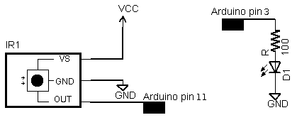
thanks to http://www.arcfn.com/2009/08/multi-protocol-infrared-remote-library.html for this drawing
I used the prototype shield, which is probably overkill but made a nice compact unit. I bent the receiver and yellow/green LEDs so they pointed towards the user. The IR tx diode is mounted on the back edge and points towards the TV. I put on a reset switch because it is always nice to have a wave to recover.
This project proved way more difficult than i expected. The device is both a reciever and a transmitter, and needed to detect IR transmission as an interrupt because I was running a timer from last activity. Combining these three functions was tricky. There was an IR library on Arduino playground http://www.arduino.cc/cgi-bin/yabb2/YaBB.pl?num=1176098434 , that was based on delay(),. The receiver worked just fine, but the transmitter failed to control the TV. I experimented for hours and finally discovered that the timing of the bits in the Arduino were off. I had to set the times much shorter than the spec, because the Arduino was timer and interrupts were slowing things down. In the process of debugging and googling help, the http://www.arcfn.com/2009/08/multi-protocol-infrared-remote-library.html library bubbled up through google and i downloaded it. This is much more solid and uses the PWM as the timing reference for transmit, so the TV liked it. Luckily it supports the same devices that I had in my home, so I used it almost unmodified. I had further troubles with the sending routine stopping the receiving routine, which the author admits to in his blog comments. All you have to do is restart the receiver after you have transmitted. I had further troubles with ambient IR triggering the receiver, and had to add a code filter to ignore anything that doesn't match a valid IR code from either the TiVo (NEC codes) or Sony.
So here is the code I ended up with. you need to download the IR library and put it in your libraries folder.
This code has debugging to the serial monitor included, which helps you understand what is happening.
Code follows....
The purpose of this project is automatically turn on the sleep timer of the television.
Story: My wife is an insomniac and stays up late every night watching TV. She eventually falls asleep and leaves the TV on. She NEVER remembers to set the sleep timer, plus the TiVo remote doesn't allow setting the TV sleep timer, and who knows where the original TV remote is most of the time. We have DirecTV, and about 3 or 4 in the morning they do a download. The TV goes black and quiet for a while, then comes back to life when the download is done. This wakes me up every night and i have to get out of bed and turn off the TV because my wife as fallen asleep and lost the remote in the bed somewhere. Arrrgh!
How it works: Based on an Arduino board, it has an IR receiver ripped from an old broken TV, and an IR diode from a remote from a TV we don't have anymore. The device sits on the TV stand, directly in front of the TV. When it detects IR traffic from the remote, it keeps resetting a timer. If the timer expires, it assumes that the user has fallen asleep and is no longer controlling the TV. The device then sends a remote control to the TV to set the sleep timer. If the user doesn't notice (they are likely asleep), the sleep timer counts down and shuts off the TV. You might ask why don't I just send a power command? Problem is I can't really be sure the TV is on or off. What if she actually turned the TV off before falling asleep. It would be a disaster to have the device turn ON the TV. Using the sleep timer is the perfect fail safe. If the TV is off, the sleep command does nothing . If the TV is on, it will count down and turn off. Just takes a little longer than turning it off directly.
We have a SONY Bravia TV and use a DirecTV TiVo box primarily. This works for those devices. You will have to modify for your devices.

Arduino TV IR sleeper
The project is constructed of:
- Arduino Duemilanove, $25-30, bought this one from http://www.sparkfun.com/commerce/product_info.php?products_id=666
- Protoshield Board $6 http://www.adafruit.com/index.php?main_page=product_info&cPath=17_21&products_id=55 . I just got the board because i had some pin headers laying around. You can always get these http://www.adafruit.com/index.php?main_page=product_info&cPath=17_21&products_id=85 while you are at it if you don't have any. I like this kit for $12.50 that will give you the board, LEDs, headers, and a reset switch. http://www.adafruit.com/index.php?main_page=product_info&cPath=17_21&products_id=51
- Yellow and Green LEDs, and 2K resistors. Used larger resistors so the LEDs weren't so bright at night in the bedroom
- IR LED and 200 ohm resistor. I broke open an old IR remote control and un-soldered it. I'm sure you can buy one if you have to. Radio shack has http://www.radioshack.com/search/index.jsp?kwCatId=&kw=ir%20diode&origkw=ir%20diode&sr=1
- IR Receiver. I scrounged this from an old broken TV set. You can even get these at Radio Shack http://www.radioshack.com/product/index.jsp?productId=2049727 for $4.
- Software - based it on this IR remote library, which is far and above the best one on the web. http://www.arcfn.com/2009/08/multi-protocol-infrared-remote-library.html
- A 9V AC adapter. I used one from a broken router, needs to be 500mA and 9V. You can use up to 12V, but it can make the Arduino hot. I've used adapters down to 6V, and they have been fine too.
Connections:
The IR receivers have three pins. Signal, Gnd, 5V. I attached it to pin 9
int RECV_PIN = 9; //IR detector module attached here
int led_green = 11; //led to indicate TV on & IR activity flickers green. Connect the same way as the IR diode, but use a 2.2K resistor in series instead
int led_yellow = 13; //led to indicated TV user is drowsy. Same as led_green.
thanks to http://www.arcfn.com/2009/08/multi-protocol-infrared-remote-library.html for this drawing
I used the prototype shield, which is probably overkill but made a nice compact unit. I bent the receiver and yellow/green LEDs so they pointed towards the user. The IR tx diode is mounted on the back edge and points towards the TV. I put on a reset switch because it is always nice to have a wave to recover.
This project proved way more difficult than i expected. The device is both a reciever and a transmitter, and needed to detect IR transmission as an interrupt because I was running a timer from last activity. Combining these three functions was tricky. There was an IR library on Arduino playground http://www.arduino.cc/cgi-bin/yabb2/YaBB.pl?num=1176098434 , that was based on delay(),. The receiver worked just fine, but the transmitter failed to control the TV. I experimented for hours and finally discovered that the timing of the bits in the Arduino were off. I had to set the times much shorter than the spec, because the Arduino was timer and interrupts were slowing things down. In the process of debugging and googling help, the http://www.arcfn.com/2009/08/multi-protocol-infrared-remote-library.html library bubbled up through google and i downloaded it. This is much more solid and uses the PWM as the timing reference for transmit, so the TV liked it. Luckily it supports the same devices that I had in my home, so I used it almost unmodified. I had further troubles with the sending routine stopping the receiving routine, which the author admits to in his blog comments. All you have to do is restart the receiver after you have transmitted. I had further troubles with ambient IR triggering the receiver, and had to add a code filter to ignore anything that doesn't match a valid IR code from either the TiVo (NEC codes) or Sony.
So here is the code I ended up with. you need to download the IR library and put it in your libraries folder.
This code has debugging to the serial monitor included, which helps you understand what is happening.
Code follows....
Links to Arduino based TV-B-Gone
Just making note of this link to an Arduino TV-B-Gone, since i have the hardware built already i'll probably have to try this. I've used his IR library and it works very well. Some of the other code out there relies on delays and breaks when the Arduino is busy.
http://www.arcfn.com/2009/12/tv-b-gone-for-arduino.html
Adafruit posted a kit, which of course i could just build, but what fun is that?
http://www.ladyada.net/make/tvbgone/design.html
They have a nice schematic drawn of the fanout to multiple IRLEDs. I'm going to check up on the current, surprised there is no series resistor on the output LEDs
Subscribe to:
Posts (Atom)