I'm in the midst of writing the control program for an Ardunio powered CNC machine.
I've decided I'll use SVG format to drive the CNC machine from the PC.
I can generate SVG files from other pictures with this online free tool:
http://www.autotracer.org/
This tool allows you to view and edit them, and draw my own directly.
http://svg-edit.googlecode.com/svn/branches/2.6/editor/svg-editor.html
Here is the spec on the SVG file format
http://www.w3.org/TR/2011/REC-SVG11-20110816/paths.html#PathDataMovetoCommands
This is the SVG for a little graphic with some letters and a square I made.
<?xml version="1.0" standalone="yes"?>
<svg width="161" height="150">
<path style="fill:#ffffff; stroke:none;" d="M0 0L0 150L161 150L161 0L0 0z"/>
<path style="fill:#010101; stroke:none;" d="M1 1L1 109L117 109L117 1L1 1z"/>
<path style="fill:#ffffff; stroke:none;" d="M3 3L3 107L115 107L115 85C87.676 91.5053 87.5147 47.4563 115 54L115 3L3 3z"/>
<path style="fill:#010101; stroke:none;" d="M41 43L41 85L49 85L49 69C54.56 69 61.8856 70.2342 66.9568 67.5432C74.8268 63.3671 75.3453 49.6136 67.956 44.7423C61.5192 40.4989 48.4628 43 41 43M80 43L80 50L88 50L88 43L80 43z"/>
<path style="fill:#ffffff; stroke:none;" d="M49 50L49 62C66.8383 61.9882 66.8383 50.0118 49 50z"/>
<path style="fill:#010101; stroke:none;" d="M80 54L80 85L88 85L88 54L80 54z"/>
<path style="fill:#ffffff; stroke:none;" d="M107.043 59.9707C98.9687 61.792 101.299 81.8813 109.794 79.1489C117.684 76.611 116.364 57.8683 107.043 59.9707z"/>
</svg>
This builds on stuff in these previous posts.
The major pieces are
-Open and read in svg files
-Parse them line by line to pull out the graphics commands
-Draw the vectors/curves on the screen
-Write out the CNC machine commands to the serial interface. That program is already written but needs to be integrated.
Having some compatibility problems with the various svg editors.
I like the files autotracer.org makes, but svg-edit.googlecode.com can't read them. GIMP will import and display them just fine. internet explorer doesn't like them either, and displays a blank page. The files from svg-edit.googlecode.com have a lot of complex commands in them.
Figured out that I want to just use the path tool in svg-edit.googlecode.com. The format is a bit different though.
svg-edit gives me this:
<path id="svg_11" d="m367,98l121,8l3,71l33,-118" stroke-linecap="null" stroke-linejoin="null" stroke-dasharray="null" stroke="#ff0000" fill="#ffffff"/>
<path style="fill:#c1bfb3; stroke:none;" d="M119 16L120 17L119 16z"/>
Played around a bit, and svg-edit seems to make files that gimp renders better.
Pushing forward, I'll try to interpret both styles.
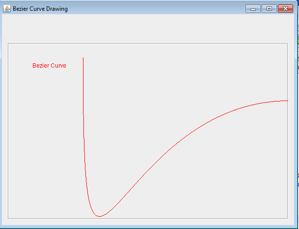
Wrote the file handling and parsing code in Java, now I need to write the graphics so I can draw a picture on the screen to see what the cnc thinks it's going to draw. That is the best way to see if I've translated the file properly too.
This took days and days to get right. Starting with some simple pictures of curves drawn in svg-edit through some vectorized complex pictures I eventually got this to work! I had some trouble with the relative curve commands and decoding the curve commands and the compound commands. The code gets over complicated and handling the absolute and relative syntax from the different svg file generators took a while to sort out.
This took days and days to get right. Starting with some simple pictures of curves drawn in svg-edit through some vectorized complex pictures I eventually got this to work! I had some trouble with the relative curve commands and decoding the curve commands and the compound commands. The code gets over complicated and handling the absolute and relative syntax from the different svg file generators took a while to sort out.

The program opens an svg file, and then parses the commands into path lists of points. Curves are expanded into lists of points for the CNC machine to draw. Java graphics draw the lists of points so I can see if it looks right.
Things I learned:
The code at this point is posted at
https://code.google.com/p/arduino-java-xyzcnc/downloads/list
Here is the steps to make a vector image file
I'm finding that svg-edit doesn't like the autotracer.org files if opened directly. Also svg-edit works better in internet explorer than chrome (where is pretty broken). If you hit the <svg> button and hand paste the .svg file from autotracer.org into svg-edit, it seems to work. Not sure what the syntax issue is, something in the headers.
Here i show editing the svg file:
notes for my to do list.
Things I learned:
- c commands have all the points relative to the starting point, not the last point in the list.
- m is absolute if first in line, relative if later in line
- if m shows up mid line, need to lift the pen and start a new line. at that point. Also true of M
The code at this point is posted at
https://code.google.com/p/arduino-java-xyzcnc/downloads/list
Here is the steps to make a vector image file
 |
| First I just used power point to make some text. This could come from anywhere. |
 |
| Then I cut and pasted the words into gimp and saved it as a .png graphics file. Again the png/gif/etc could come from any source |
 |
| Then I went to autotracer.org and uploaded the file. Hit send file and then download the resulting .svg file from the top. |
 |
| Then I used my Java program to open the .svg file, filter and plot it to the screen. W00t! It worked!!! Now I have a vector file that I can send to the CNC machine. |
I'm finding that svg-edit doesn't like the autotracer.org files if opened directly. Also svg-edit works better in internet explorer than chrome (where is pretty broken). If you hit the <svg> button and hand paste the .svg file from autotracer.org into svg-edit, it seems to work. Not sure what the syntax issue is, something in the headers.
Here i show editing the svg file:
 |
| Open the file in internet explorer, svg-edit. Did this by pasting the previous svg into the text window. Edited it and moved some words. |
 |
| Wrote out a new svg file. This time the commands are all in relative syntax. |
 |
| It works! Here it is in the Java program. |
notes for my to do list.
- Need to fix Java graphics repaint - DONE (added overide of paint to redo the drawing)
- Get rid of all the system.out.println's for debug - DONE
- need to make background non-white because some lines are disappearing. - DONE
- Also need to smarten up the calculation for how many segments I linearize the curves - DONE
Now to combine it with the CNC control java program...
This post is in progress....