Search This Blog

Saturday, March 26, 2011

Notes on Learning to Make a Java GUI for the CNC machine

Not sure if this is the way I will go, but I'm exploring using Java to create a small GUI to control the Arduino based XYZ CNC machine.  I did see some folks have already done this, so I may go back and use their code.
This is a place to store my notes as I explore this topic.

My hardware is an Arduino with two motor shields from Adafruit attached (see my post on modding the shield to stack) and another Arduino reading three rotary encoders (see my post on this).  These control a Zen toolworks 7x7 CNC machine.

I've written the code for the Arduino to respond to serial commands to move in straight line at constant velocity from current location to a new location.   Ideally this is all that ever needs to run on the Arduino.  I wrote a simple HPGL interpretor, but the serial communication wasn't working out. When I used the Arduino GUI to dump a serial file to the Arduino, the Arduino did not process the commands fast enough, obviously it has to move motors, etc, and the serial input would overrun the input buffer in the Arduino and trash the data.  The Arduino can't do this job all by itself.  i will never be able to send a whole HPGL file to the Arduino, it needs to be passed a bit at a time by a PC program.

So the goal here is to write a GUI that will allow the PC to feed the Arduino a file a bit at a time, and also have manual buttons to move the motors and display the encoder postions.  Maybe even the limit switches.  All the arduino will do is move from X,Y,Z to X,Y,Z point as commanded.

Downloaded Netbeans and Java JDK here:
https://cds.sun.com/is-bin/INTERSHOP.enfinity/WFS/CDS-CDS_Developer-Site/en_US/-/USD/ViewFilteredProducts-SingleVariationTypeFilter

Found some information on talking to the serial port here:
http://java.sun.com/developer/Books/javaprogramming/cookbook/11.pdf

That book says I may need to download the Java Communication API, which I found here
http://www.oracle.com/technetwork/java/index-jsp-141752.html
but this looks to be for LINUX only.  The text says for windows...
  To use that, download javax.comm for the 'generic' platform (which provides the front-end javax.comm API only, without platform specific back-end implementations bundled). Then acquire the Windows binary implementation rxtx-2.0.7pre1 from http://www.rxtx.org.


Found a web page with specific instructions!  Here:
http://pradnyanaik.wordpress.com/2009/04/07/communicating-with-ports-using-javaxcomm-package-for-windows/

So I registered at sun and downloaded the generic package java communication API
https://cds.sun.com/is-bin/INTERSHOP.enfinity/WFS/CDS-CDS_SMI-Site/en_US/-/USD/ViewFilteredProducts-SingleVariationTypeFilter

Now I'm puzzled, only the comm.jar file is there, not the win32com.dll or the javax.comm.properties

Found another example that seems more clear;
http://edn.embarcadero.com/article/31915
Points to the same oracle page that got me only comm.jar.  hmmmm.
And rxtx.org points to a isp dead end page.

Friend sent me rxtx-2.1-7-bins-r2  dont know where he got it.  But no worries, it is on the web see below
Instructions were similar, but now i had a jar file and a dll.
README referred to this web page, which had the files on it
http://rxtx.qbang.org/wiki

Windows
RXTXcomm.jar goes in \jre\lib\ext (under java)
rxtxSerial.dll goes in \jre\bin

Then went here to use in netbeans
http://rxtx.qbang.org/wiki/index.php/Using_RXTX_In_NetBeans
I did the right click on libraries to add the jar file but i had already copied the files into the locations above, so i think i'm done

Went to the sample project
http://rxtx.qbang.org/wiki/index.php/Documented_interface_to_communicate_with_serial_ports_for_beginners,_including_example_project
Even mentions arduinos - w00t
downloaded the zip file  RXTXexample.zip
Bleh, not really sure how to use this with netbeans.  README talks about ant in linux.
Tried opening as a project in netbeans...no dice

Opened the project my friend sent, myRxTxTest2.  I will go back and figure out how he made this later, sorry for the trail that can't be followed.  Here is the basic Java code that makes up Main.java.  There is
also a GUI form that goes with it, but nothing earth shaking there.

//--------------------------------------------------------------------------------------------------
import java.io.*;
import java.util.*;
import gnu.io.*;
import java.awt.event.MouseAdapter;
//import javax.comm.*;
/**
 *
 * @author eric
 */
public class RealMain {
    Enumeration      portList;
    CommPortIdentifier portId;
    SerialPort      serialPort;
    OutputStream       outputStream;
    InputStream         inputStream;
    boolean      outputBufferEmptyFlag = false;
    Thread             readThread;
    Thread              writeThread;
    boolean             wrFlag=true;
    boolean             rdg=true;
    String              msgin;
    String              msginmod;


    public void Go(){
        //inForm inf = new inForm("MyForm");
        //inf.go();
        trash trh = new trash();


        trh.setVisible(true);


        try{
            portId= CommPortIdentifier.getPortIdentifier("COM11");
        }catch(Exception e){
            System.out.println("Error getting port ID"+ e);
            Enumeration ports = CommPortIdentifier.getPortIdentifiers();


            //tomw - addeed dump of all active ports
            System.out.println("Active ports found:");
            while(ports.hasMoreElements()){
                CommPortIdentifier port = (CommPortIdentifier) ports.nextElement();
                System.out.println(port.getName());
            }
        }
        try{
            serialPort = (SerialPort) portId.open("My RxTx test", 2000);
            System.out.println("Got Serial Port Open");
            System.out.println("type something in the console window to send it (15 characters max) - type exit to quit ");
        }catch(Exception e){
            System.out.println("Error opening port "+ e);
            System.exit(1);
        }
        try {
            outputStream = serialPort.getOutputStream();
        } catch (IOException e) {
            System.out.println("Error setting output stream "+e);
        }
        try {
            inputStream = serialPort.getInputStream();
        } catch (IOException e) {
            System.out.println("Error setting input stream "+e);
        }
        try {
            serialPort.setSerialPortParams(9600,
                                           SerialPort.DATABITS_8,
                                           SerialPort.STOPBITS_1,
                                           SerialPort.PARITY_NONE);
        } catch (UnsupportedCommOperationException e) {}


        ReadHandler RH = new ReadHandler();
        Thread RT = new Thread(RH);
        RT.start();
        InputStreamReader cmlIn = new InputStreamReader(System.in);
        BufferedReader brIn = new BufferedReader(cmlIn);
        PrintWriter pr = new PrintWriter(outputStream,true);
        while (rdg){
            try{
                msgin = brIn.readLine();
                System.out.println("You typed "+ msgin);
                try{                  
                    //pr.print(msgin);
                    //outputStream.write('w');
                    //outputStream.write(0x000a);
                   // pr.print(0x00);
                   // pr.println();
                    if(msgin.length()>15){
                        msginmod=msgin.substring(0, 15);
                        System.out.println("more than 15 characters - will truncate to " + msginmod);
                    }else{
                        msginmod=msgin;
                    }
                    pr.println(msginmod);
                }catch(Exception e){
                    System.out.println("error writing to device "+ e);
                }
                if (msgin.equalsIgnoreCase("exit")){
                    rdg=false;
                    System.out.println("leaving now");                
                    outputStream.close();
                    inputStream.close();
                    brIn.close();
                    pr.close();
                    serialPort.close();
                    System.exit(1);
                }
            }catch(Exception e){
                System.out.println("error reading line"+ e);
            }
        }
    }
    public void Write(){
        System.out.println("got here");
    }


    class ReadHandler implements Runnable {
        volatile boolean on;      
        public void run(){
            int c;
            String msgback;
            InputStreamReader IS = new InputStreamReader(inputStream);
            BufferedReader BR = new BufferedReader(IS);
            while(rdg){
                try{
                    msgback=BR.readLine();
                    System.out.println("line back is "+ msgback);
                }catch(Exception e){
                    //tomw - commented out, screen if filling with this message
                    //System.out.println("error reading back"+ e);
                }
            }
        }
    }


}
//--------------------------------------------------------------------------------------------------------

It complained it had non existing paths to my friends RXTXcomm.jar and others.  Trying to point it to my own files
OK - found that right click on Libraries in the project tree, hit properties, brings up the GUI to remove the broken links.  Still missing java.boot.jar  looks like i can ignore this.  Complains the port doesn't exist.
looks like the code points to a port /dev/ttySO, since he uses Linux, I'm still using windows. trying this instead:
Found some code at the bottom of this page that tells how to read what ports are active:
http://stackoverflow.com/questions/274179/nosuchportexception-using-rxtx-java-library-on-windows

    Enumeration ports = CommPortIdentifier.getPortIdentifiers();  

    while(ports.hasMoreElements()){  
        CommPortIdentifier port = (CommPortIdentifier) ports.nextElement();
        System.out.println(port.getName());
    }
}  


Bingo - I get:

COM1
COM11
LPT1

So changing the port to "COM11" where my Arduino is and error goes away, but the form flashes up then disappears immediately from within Netbeans, Duh - the arduino app was open and the port was busy.
Closed it and things are looking up!

For testing I made a tiny sketch for the Arduino to respond to serial inputs, turns off LED, etc

//-------------------------------------------------------------------------------------

// Test program for the Arduino
// for development of a serial interface GUI on the PC
// Just makes communication on the serial interface


char inByte = '0';         // incoming serial byte
char outByte = '0';        // outgoing serial byte
boolean contact = false;    //indicates a link partner was found


void setup()
{
  // start serial port at 9600 bps:
  Serial.begin(9600);
  pinMode(13, OUTPUT);    
}


void loop()
{
  if (Serial.available()) {
    contact = true;
    inByte = Serial.read();
    
    if (inByte == 'U') digitalWrite(13, HIGH);   // set the LED on
    if (inByte == 'D') digitalWrite(13, LOW);    // set the LED off
    
    // mess with it a bit to show something happened
    outByte = inByte + 1;
    Serial.println(outByte);         
  } else {
    //spew junk to let the world know you want to talk
    if (!contact)   Serial.print(",");
  }
  
}

//-------------------------------------------------------------------

OK, some success.  The console window shows the responses from the Arduino.  The form is not working but at least it is talking to the Arduino from the Java console!!!  w00t!

Had to switch to my laptop, so brief recap of what i had to do to get netbeans back to this point.....
Download Java netbeans JDK
Download Java Communication API, and get the file comm.jar from the generic platform
Download  rxtx-2.1-7-bins-r2 from http://rxtx.qbang.org/wiki and put the RXTXcomm.jar and rxtxSerial.dll in the folders in netbeans where the README says
OK - back to our show.....

Have the very basics of the GUI working now by splicing together demo GUI program with the rxtx.   I can push a button on the GUI, send a 'U' to the serial interface and turn on the LED.   Awesome!  'D' turns it off.   The port initialization was stolen directly from the code i posted further up.   The Arduino sends back the position and the GUI displays it.  Left a place for the encoders to read back, that requires more work from a second serial port.


Using the basic GUI builder in Netbeans.  The form is just made with the form builder and the functions pasted into it's fields.

I'm in business.  Now the drudgery of making the full GUI, passing coordinate messages, spooling a HPGL file, etc to the real Arduino stepper motor control program.   I'll spare some details until I have a more complete interface put together and write that up.

Here is the Java and the Arduino programs.

package Serial_Comm_GUI;


//imports all the java rxtx libs
import java.io.*;
import java.util.*;
import gnu.io.*;
import java.awt.event.MouseAdapter;
//import javax.comm.*;


/**
 *
 * @author tomw
 */
public class RealMain {
    Form1 myform;
    boolean toggle = false;
    Enumeration      portList;
    CommPortIdentifier portId;
    SerialPort      serialPort;
    OutputStream       outputStream;
    InputStream         inputStream;
    boolean      outputBufferEmptyFlag = false;
    Thread             readThread;
    Thread              writeThread;
    boolean             wrFlag=true;
    boolean             rdg=true;
    String              msgin;
    String              msginmod;
    String              portName = "COM11";


    public void go() {


        // Pops up the GUI
        myform = new Form1(this);
        myform.setVisible(true);


        myform.setLabel2(portName);
        myform.setLabel11("contacting...");
        myform.setLabel7("contacting...");


        // Opens the serial port and configures it, handles errors
        try{
            portId= CommPortIdentifier.getPortIdentifier(portName);
            System.out.println(portName);
        }catch(Exception e){
            System.out.println("Error getting port ID"+ e);
            Enumeration ports = CommPortIdentifier.getPortIdentifiers();


            //tomw - addeed dump of all active ports
            System.out.println(portName);
            System.out.println("Port not Found - Active ports found:");
            while(ports.hasMoreElements()){
                CommPortIdentifier port = (CommPortIdentifier) ports.nextElement();
                System.out.println(port.getName());
            }
        }
        try{
            serialPort = (SerialPort) portId.open("My RxTx test", 2000);
            System.out.println("Serial Port Open");
            System.out.println("type in the console window to send commands");
        }catch(Exception e){
            System.out.println("Error opening port "+ e);
            System.exit(1);
        }
        try {
            outputStream = serialPort.getOutputStream();
        } catch (IOException e) {
            System.out.println("Error setting output stream "+e);
        }
        try {
            inputStream = serialPort.getInputStream();
        } catch (IOException e) {
            System.out.println("Error setting input stream "+e);
        }
        try {
            serialPort.setSerialPortParams(9600,
                                           SerialPort.DATABITS_8,
                                           SerialPort.STOPBITS_1,
                                           SerialPort.PARITY_NONE);
            myform.setLabel11("0:0:0");
        } catch (UnsupportedCommOperationException e) {}


        ReadHandler RH = new ReadHandler();
        Thread RT = new Thread(RH);
        RT.start();
        InputStreamReader cmlIn = new InputStreamReader(System.in);
        BufferedReader brIn = new BufferedReader(cmlIn);


    }


    public void longTextChange() {
        if (toggle == false) {
            myform.setLabel2("Oops!");
            toggle = true;
        } else   {
            myform.setLabel2("Ahhhh!");
            toggle = false;
        }
        System.out.println("You pushed me!!");
    }
    public void pushedUp(){
        PrintWriter pr = new PrintWriter(outputStream,true);
        pr.println('U');
        System.out.println("Up");
    }
    public void pushedDown(){
        PrintWriter pr = new PrintWriter(outputStream,true);
        pr.println('D');
        System.out.println("Down");
    }
    public void pushedRight(){
        PrintWriter pr = new PrintWriter(outputStream,true);
        pr.println('R');
        System.out.println("Right");
    }
    public void pushedLeft(){
        PrintWriter pr = new PrintWriter(outputStream,true);
        pr.println('L');
        System.out.println("Left");
     }
    public void pushedZup(){
        PrintWriter pr = new PrintWriter(outputStream,true);
        pr.println('Z');
        System.out.println("Z up");
     }
    public void pushedZdown(){
        PrintWriter pr = new PrintWriter(outputStream,true);
        pr.println('W');
        System.out.println("Z down");
     }


    class ReadHandler implements Runnable {
        volatile boolean on;
        public void run(){
            int c;
            String msgback;
            InputStreamReader IS = new InputStreamReader(inputStream);
            BufferedReader BR = new BufferedReader(IS);
            while(rdg){
                try{
                    msgback=BR.readLine();
                    System.out.println("Position "+ msgback);
                    myform.setLabel11(msgback);
                }catch(Exception e){
                    //tomw - commented out, screen if filling with this message
                    //System.out.println("error reading back"+ e);
                }
            }
        }
    }
}


//--------------------------------------------------------------------------------------------------------------------------------


// Test program for the Arduino
// for development of a serial interface GUI on the PC
// Just makes communication on the serial interface


char inByte = '0';         // incoming serial byte
char outByte = '0';        // outgoing serial byte
boolean contact = false;    //indicates a link partner was found
int stepperX = 0;
int stepperY = 0;
int stepperZ = 0;


void setup()
{
  // start serial port at 9600 bps:
  Serial.begin(9600);
  pinMode(13, OUTPUT);    
}


void loop()
{
  if (Serial.available()) {
    contact = true;
    inByte = Serial.read();
    
     switch( inByte ) {
      case 'U' : 
        digitalWrite(13, HIGH);   // set the LED on
        stepperY++;
        break;
      case 'D' : 
        digitalWrite(13, LOW);    // set the LED off
        stepperY--;
        break;
      case 'R' : 
        for( int i=0; i<3 ; i++) {
          digitalWrite(13, LOW);    // set the LED off
          delay(300);
          digitalWrite(13, HIGH);    // set the LED on
          delay(300);
        }
        stepperX++;
        break; 
      case 'L' : 
        for( int i=0; i<5 ; i++) {
          digitalWrite(13, LOW);    // set the LED off
          delay(100);
          digitalWrite(13, HIGH);    // set the LED on
          delay(100);
        }    
        stepperX--;    
        break;    
      case 'Z' : 
        for( int i=0; i<10 ; i++) {
          digitalWrite(13, LOW);    // set the LED off
          delay(50);
          digitalWrite(13, HIGH);    // set the LED on
          delay(50);
        }        
        stepperZ++;
        break;  
      case 'W' : 
        for( int i=0; i<10 ; i++) {
          digitalWrite(13, LOW);    // set the LED off
          delay(50);
          digitalWrite(13, HIGH);    // set the LED on
          delay(150);
        }  
        stepperZ--;       
        break;   
      default :
        // ignore unknown letter command
        break;
     }
    
    Serial.print(stepperX);Serial.print(":");Serial.print(stepperY);Serial.print(":");Serial.println(stepperZ);    
  } else {
    //spew junk to let the world know you want to talk
    if (!contact)   Serial.print(",");
  }
  
}


Wednesday, March 16, 2011

Arduino XYZ CNC Carving Machine Control Software

Working on control software for the CNC machine.

Wrote a basic program to do linear interpolation from coordinates received over the serial interface.  Now I need to find an easy way to send coords from a graphics program.

Trying to decide what I need to write so that I can communicate with some open source machine control software.  The Arduino can't do a lot on it's own, but it needs to interpret commands.

Looks like some machines support HPGL code.  That is reasonably simple to implement but will require writing several functions.  It is a short term solution

This guy made an HPGL GUI
http://www.linuxcnc.org/component/option,com_kunena/Itemid,20/func,view/catid,31/id,1870/lang,english/
www.securetech-ns.ca/camm-linux.html

Many graphics programs can output HPGL.  This will be for mostly 2D projects, like PCB cutting.

this guy wrote an HPGL interpretor, that i looked at for ideas, but didn't end up trying to use it
http://sensi.org/~svo/motori/

This page has a simple HGL file that I used for test
http://www.winline.com/evalpen_center.html
http://www.winline.com/images/plotfiles/GL-C-O.plt

Wrote this very basic HPGL control layer to interface from basic HPGL commands to control the adafruit motor shield:
The bug i have right now is that if i send the very long coord lists in this file, i fill the Arduino serial buffer and it hoses the data, since the Arduino has to move the motors, reading the data as it comes doesn't quite work. Meanwhile this is what i have so far, that works will with manually entered commands.


 // Stepper Motor Control Program
// For an XYZ stepper motor controller
// Receives serial commands from PC, controls 3 motor CNC machine
// Interprets basic HPGL style instructions
// Tom Wilson 2011

#define INCH 4000 //steps per inch of the machine = threads per inch * steps per rotation
#define RPM 30 //speed of the motors
#define SER_HEADER 'G' // Header tag for serial message

// Adafruit Motor shield library
// modified by tomw to drive 2 shields at once
// This requires a modified library
//with the second having MOTORLATCH on pin 13, renamed MOTORLATCHA
//and all functions renamed to A versions
#include <AFMotor.h>
#include <AFMotorA.h>

//Set up the steps per revolution and location of motors
AF_Stepper motorX(200, 1);
AF_Stepper motorY(200, 2);
AF_StepperA motorZ(200, 2);

// Set up the basic machine position variable
signed long int Xpos = 0;
signed long int Ypos = 0;
signed long int Zpos = 0;

// Set up the destination machine position variable
signed long int newXpos = 0;
signed long int newYpos = 0;
signed long int newZpos = 0;

// Set up global place to keep serial values
signed long int newSerialData;
bool XorY = false;

void setup() {
  Serial.begin(9600); // set up Serial library at 9600 bps
  Serial.println("Stepper Controller Online");

  //set the default speed of the motors
  motorX.setSpeed(RPM); ;
  motorY.setSpeed(RPM); ;
  motorZ.setSpeed(RPM); ;

  delay(1000); // wait for the supply to come up

  //step motors one step and back to power the coils
  motorX.step(1, FORWARD, SINGLE);
  motorY.step(1, FORWARD, SINGLE);
  motorZ.step(1, FORWARD, SINGLE);
  motorX.step(1, BACKWARD, SINGLE);
  motorY.step(1, BACKWARD, SINGLE);
  motorZ.step(1, BACKWARD, SINGLE);

  // Home position
  Xpos = 0;
  Ypos = 0;
  Zpos = 0;
  newXpos = 0;
  newYpos = 0;
  newZpos = 0;

  Serial.print("Current:");
  Serial.print("\tX:");
  Serial.print(Xpos);
  Serial.print("\tY:");
  Serial.print(Ypos);
  Serial.print("\tZ:");
  Serial.println(Zpos);

  Serial.println("Ready for Commands");
}

void loop() {
  while(Serial.available() ) {
    // Loop simply accepts commands from serial and executes them
    readHPGLcommand();               //read the command

  }
}


void readHPGLcommand() {
  // reads serial port for two letter HPGL command and optional coords that follow
  char c;
  bool coord_avail;

  //make sure there is enough data there for form a command, at least "IN;"
  if(Serial.available()>=3){
  
    c = Serial.read();
 
    // Interpret HPGL command, ingnore unsupported commands and whitespace
    //http://paulbourke.net/dataformats/hpgl/    has definitions
    switch( c ) {
      case 'P' :
          switch( Serial.read() ) {
            case 'U' :  // PU Pen Up
              Serial.println("Pen Up  \t/\\ /\\ /\\ /\\");   //lift pen and optionally move to new coords
              zMove(50);
              // expect either nothing or pairs of coords to follow
              XorY = true;
              coord_avail = true;
              while( coord_avail ) {  
                coord_avail = readSerialNumber();
                // hack to alternate reading values as X or Y
                if ( XorY) {
                  newXpos = newSerialData;
                  XorY = false;
                } else {
                  newYpos = newSerialData;
                  XorY = true;
                  Serial.print(newXpos); Serial.print(":"); Serial.print(newYpos); Serial.print("\t>>");
                  linearInterpolationMove( newXpos, newYpos);
                }
              }
              break;
            case 'D' :  // PD Pen Down
              Serial.println("Pen Down\t\\/ \\/ \\/ \\/");  //drop pen and optionally move to new coords
              zMove(0);
              coord_avail = false;
              // expect either nothing or pairs of coords to follow            
              XorY = true;
              coord_avail = true;  //need to make sure the loop goes at least once
              while( coord_avail ) {  
                coord_avail = readSerialNumber();
                // hack to alternate reading values as X or Y
                if ( XorY) {
                  newXpos = newSerialData;
                  XorY = false;
                } else {
                  newYpos = newSerialData;
                  XorY = true;
                  // only valid coord if two values were found
                  Serial.print(newXpos); Serial.print(":"); Serial.print(newYpos); Serial.print("\t>>");
                  linearInterpolationMove( newXpos, newYpos);
                }
              }
  
              break;
            case 'G' :  // PG Page Feed
              Serial.println("Page Feed");
              while( readSerialNumber() ) {}    //keep reading until coords or ';' is found
              // Command doesn't do anything yet
              break;
            case 'T' :  // PG Pen Thickness
              Serial.println("Pen Thickness");
              while( readSerialNumber() ) {}    //keep reading until coords or ';' is found
              // expects one number to be returned, indicating pen
              Serial.print("Pen Thickness Set to:");
              Serial.println(newSerialData);
              // currently not doing anything with this command
              break;
            default :
              Serial.println("WARNING: Unknown command Px ignored");
              while( readSerialNumber() ) {}    //keep reading until coords or ';' is found
              break;
          }
          break;
      case 'I' :
          switch( Serial.read() ) {
            case 'N' :  // IN Initialize
              Serial.println("Initialize");
              while( readSerialNumber() ) {}    //keep reading until coords or ';' is found
              // Home position
              Xpos = 0;
              Ypos = 0;
              Zpos = 0;
              break;
            default :
              Serial.println("WARNING: Unknown command Ix ignored: ");
              while( readSerialNumber() ) {}    //keep reading until coords or ';' is found
              break;
          }
          break;
      case 'S' :
          switch( Serial.read() ) {
            case 'P' :  // SP Select Pen
              Serial.println("Select Pen");
              while( readSerialNumber() ) {}    //keep reading until coords or ';' is found
              // expects one number to be returned, indicating pen
              Serial.print("Pen set to:");
              Serial.println(newSerialData);
              // currently not doing anything with this command
              break;
            default :
              Serial.print("WARNING: Unknown command Sx ignored: ");
              while( readSerialNumber() ) {}    //keep reading until coords or ';' is found
              break;
          }
          break;  
      default :
          //Whitespace or unrecognized letter, ignore it
          break;
    } //cmd switch
  } //if serial
}


bool readSerialNumber() {
//read coords from serial input
//commands end with ';' and lists of coords are separated by ','
//
// Three things can happen and need to differentiate
// 1) no coords at all, just a ; - need to return right away and break the calling while loop
// 2) a coordinate followed by , - need to output the coord and continue
// 3) a coordinate followed by ; - need to output the coord and break the calling while loop

  signed long int coord = 0;   //temp storage for coords from serial
  signed int sign = 1;         //temp storage for coord sign from serial
  char c;
      
       while ( c != ',' && c != ';' /*&& Serial.available()*/){
         c = Serial.read();
         if( c == '-' ) sign = -1; // capture the sign
         if( c >= '0' && c <= '9'){
           coord = (10 * coord) + (c - '0') ; // convert digits to a number
         }
       }
    
      //put the data in the top level variable
      newSerialData = coord * sign;
        
      //detect the end of command ';' after the last coord
      if( c == ';') return false;
      return true;
}


void zMove (signed long int newZ) {
  //calculates steps to move, and moves, to new Z position requested
  signed long int distance = 0;
  signed long int oldZ = Zpos;

  distance = newZ - oldZ;

  if ((distance < 8000) && (distance > -8000)) {
    if (distance >=  1)  motorZ.step(distance, FORWARD, SINGLE);
    if (distance <= -1)  motorZ.step(-1*distance, BACKWARD, SINGLE);
  } else {
    //movement requested is large and likely an error
    Serial.println("ERROR - Z axis out of range");
  }

  Zpos = newZ;  //update machine current position
}


void linearInterpolationMove ( signed long int newX, signed long int newY) {
  float distance = 0;
  int stepnum = 0;
  signed long int nextX;
  signed long int nextY ;
  signed long int oldX = Xpos;
  signed long int oldY = Ypos;

  Serial.print("\t");
  Serial.print(Xpos);
  Serial.print(":");
  Serial.print(Ypos);
  Serial.print("\t --");

  //find the hypotenuse, the total distance to be traveled
  distance = sqrt((newX - oldX)*(newX - oldX) + (newY - oldY)*(newY - oldY) );

  //round to integer number of steps that distance. Step by two to minimize 0 size steps.
  for (stepnum=0; stepnum <= (distance + 0.5); stepnum++) {

    //calculate the nearest integer points along the way
    nextX = oldX + stepnum/distance*(newX-oldX);
    nextY = oldY + stepnum/distance*(newY-oldY);

    //move machine to that new coordinate, if 0 delta, don't move

    if ((distance < 7*INCH) && (distance > -7*INCH)) { //trap crazy value
    /* removed for test
      if ((nextX-Xpos) >=  1)  motorX.step((nextX - Xpos)*INCH/1000, FORWARD, SINGLE);
      if ((nextX-Xpos) <= -1)  motorX.step((Xpos - nextX)*INCH/1000, BACKWARD, SINGLE);
      if ((nextY-Ypos) >=  1)  motorY.step((nextY - Ypos)*INCH/1000, FORWARD, SINGLE);
      if ((nextY-Ypos) <= -1)  motorY.step((Ypos - nextY)*INCH/1000, BACKWARD, SINGLE);
    */

    //update the machine current position
    Xpos = nextX;
    Ypos = nextY;
    } else {
      Serial.println("ERROR!  Distance value too big");
      break;
    }
  }

  //move machine to the exact new coordinate, because rounding makes a small error
  /* removed for test
  if ((newX-Xpos) >=  1)  motorX.step(newX - Xpos, FORWARD, SINGLE);
  if ((newX-Xpos) <= -1)  motorX.step(Xpos - newX, BACKWARD, SINGLE);
  if ((newY-Ypos) >=  1)  motorY.step(newY - Ypos, FORWARD, SINGLE);
  if ((newY-Ypos) <= -1)  motorY.step(Ypos - newY, BACKWARD, SINGLE);
  */

  //update the machine current position
  Xpos = newX;
  Ypos = newY;

  Serial.print("----> \t");
  Serial.print(Xpos);
  Serial.print(":");
  Serial.println(Ypos);
}

Sunday, March 6, 2011

Arduino based XYZ CNC Carving Machine

Starting a new thread now that I have a plan....

THE PLAN

After some poking around researching building a small CNC machine for light carving, I came to the conclusion that the Zen toolworks CNC machine was a good deal and would shave months off my project.   I figured by the time I collected steppers, lead screws, made parts etc I'd spend a more than this and get a worse result.   This kit is the stage, leadscrews and steppers.  No electronics/drivers are included.  It is fairly small but it looks like a great leg up.

Here is what I'm planning to use

Zen Toolworks CNC Carving Machine DIY Kit 7x7. 


My initial plan is to use Arduinos as the motor controllers.  I like the older Arduino, because it is a tad cheaper, and really functionally equivalent to the Uno.  Amazon for the free shipping and no tax.

Arduino Duemilanove

http://www.amazon.com/gp/product/B004A7L3NC/ref=as_li_qf_sp_asin_il_tl?ie=UTF8&tag=workingsilico-20&linkCode=as2&camp=1789&creative=9325&creativeASIN=B004A7L3NC


Most CNC software uses a computer parallel port to synchronize output bits to control the motor, and perhaps the Arduino isn't really the best solution.  However parallel ports are old and obsolete, so I'm going to make my own controller anyway.  Irrational decision probably, but buying an old parallel port board makes me nauseous.    If i can control all the motors from one Arduino, I can keep the synchronization with no work.
Motor driver controllers are way expensive and even with a coulple Arduinos and motor control boards, I'm probably coming out ahead.

Bought two motor control boards from adafruit.  A prebuilt board that saves a lot of time, from an A+ vendor.

Adafruit Motor/Stepper/Servo Shield for Arduino kit - v1.0

http://www.adafruit.com/index.php?main_page=product_info&cPath=17_21&products_id=81

I want to be able to know the position of the machine at all times.  This isn't really needed for stepper motor controlled machines, don't need feedback.   However for manual stepping and testing, I wanted a readout.
Will try to read back position via cheap rotary encoders, 
http://www.sparkfun.com/products/9117
I may just use the encoders for calibration, or monitoring.  A feedback loop solution may be overkill.  It depends on the torque and backlash of the motors.  TBD.

The arduinos will commnicate via USB to the host PC.
The software is a journey, but there is tons of stuff on the web, so we will see!


DRIVING THE MOTORS

The stepper is rated for 1.68A at 2.8V.  I'm going to have to run it at 5V, because the driver chips need at least 4.5V, and I'm using a repurposed ATX computer power supply to give me 5V.
The stepper that comes with the Zen is this one:
http://www.savebase.com/InfoBase/SAVEBASE/PKG/001520/Image/nema17%20copy.jpg
42BYGH47-401A
I understand that it can take the higher voltage, but the current will go up.  Have to be careful to not step too fast since I don't have a current limiter.  Maybe I could put a 1.3 ohm resistor in series to limit the current to 1.68A.  It would have to be a 3.6W resistor.  They are available as wirewounds for >$1.  That would add inductance for sure.  I will wait and see how it works first.
Upgraded the L293D drivers with SN754410 in the adafruit stepper motor board, it wasn't driving the stepper very well.  They are pin for pin compatible.  I will solder two together to get 2A.  Three might be even safer.  Added a heat sink too.  http://www.aavidthermalloy.com/cgi-bin/stdisp_print.pl?Pnum=580200b00000g.  Bought this at digikey.com.

Stacking the two driver chips turned out to be tricky, and after making a big solder short, and apparently ruining one driver chip, i found the method to do this.   Solder the two chips piggy back BEFORE you put them onto the pc board.  Put one in a vice, piggyback the second, then solder tack the end pins on both sides.  Then come back and one by one solder the pins together.   Then put the assembly into the PC board.

To use a computer power supply, you have to trick it to turn on like this guy shows:
http://www.youtube.com/watch?v=rivoVzxwNtI
After that, just use any of the red and black wires.  Says it will source 32A.  wow.

Set it up, used a scrounged PC power connector to plug it in, shorted the two pins as described and 5.1V, cool and quiet.  Plugged it into the stepper motor board and the Zen toolworks steppers, and it is working great.  The chips do get a bit hot, so i'm thankful for the heat sink and I'm suing the power supply fan to blow across the driver boards.

In this photo you can see the power supply, the Arduino with the motor control board on top, the double stacked driver chips and heat sinks, connected to the stepper motors.


Then i moved on and modified the Adafruit motor shield so that I could stack two shields on top of each other and control 4 motors at once (only have three right now).  Made a stand alone post for what I did here, it was so cool.   Basically a small hack to give each board it's own latch pin.  Only took one more pin to differentiate which board responds to the commands to the motors, and the other motors still hold their value.  Awesome!
http://blog.workingsi.com/2011/03/method-for-controlling-4-steppers-from.html
Arduino with two Adafruit motor shields on top, connected to the PC 5V power supply and three motors (3rd is out of the picture)

READING THE ENCODERS

Now I need to build an Arduino module with the rotary encoders and an LCD display to show the position. I will also have at least one button to set the home position.
Back to the rotary encoders from sparkfun. Some sample code is here:
http://www.circuitsathome.com/mcu/reading-rotary-encoder-on-arduino
Datasheet: http://www.sparkfun.com/datasheets/Components/TW-700198.pdf
The sample code worked out of the box, now to modify it to read three encoders.
It makes use of port manipulation to read all the input simultaneously.  This page helped http://www.arduino.cc/en/Reference/PortManipulation
Got the three encoder code working, I made a separate post for it so I could include it in the blog, look for it.
http://blog.workingsi.com/2011/02/position-sensor-for-arduino-xyz-cnc.html
I rewrote the code so it made sense to me, the example took a lot of head scratching.


Attached the three encoders to the machine temporarily, and it is working great.  Stepped over and back and it returns to the same position.  No worries about he rotary encoders missing steps.

LIMIT SWITCHES
found some small limit switches for <$2 a piece.  The plan is to use them to interrupt the jumper wire on the PC power supply, thereby killing power if the stage is going to hit the walls.   I was advised by a friend that it can be a pain to unstick yourself if you have killed the motor power, but I will turn the stage back by hand if this happens.
http://www.amazon.com/gp/product/B002P4XQY6/ref=as_li_qf_sp_asin_il_tl?ie=UTF8&tag=workingsilico-20&linkCode=as2&camp=1789&creative=9325&creativeASIN=B002P4XQY6

WRITING THE CODE

Now I have moved on to coding.   Plan is to write or borrow a simple Gcode interpreter than can run on the Arduino.   I found this page, making a note:
http://dank.bengler.no/-/page/show/5470_grbl?ref=mst

I hope to be able to use some open source software for the graphics.  Looks like the defacto is EMC2.  EMC2 is open source CNC software at http://www.linuxcnc.org/content/view/11/10/lang,en/.  I will have to use Linux ubuntu for this, but since it probably would be best to use a dedicated PC, Linux is a good choice because I can use an old PC knocking about.  Had hoped to use windows to be able to make visual basic widgets.  I'll come back to that later.   I may need to write some layer of code between the serial ports and the EMC2, since it wants to drive a parallel port and do all the thinking.  "G-code" is the format for the commands that EMC2 produces.

Found this link, he beat me to it!  Arduino controlling and translating Gcode.
http://code.google.com/p/rsteppercontroller/

I decided to start some new posts for the coding, so look there for updates

Thursday, March 3, 2011

Method for controlling 4 steppers from Arduino and two Motor Shields from Adafruit

This is so I can control the X Y and Z axis stepper motors of a CNC from one single arduino and can avoid a synchronized communication network and multiple Arduinos.  The fourth motor control will be reserved for tool adjustments if needed, it is extra for now.

I wanted to be able to allow all the motors to hold while others were running.  This hack succeeded in getting me 4 motors with full control.  I'm not attempting to microstep, I'm just using this for single stepping, I think maybe the way the library deals with microstepping it may not work because the PWM leads are shared.

Using two of these motor control boards:
http://www.adafruit.com/index.php?main_page=product_info&cPath=17_21&products_id=81

We are going to stack two motor shields on top of the Arduino.  Using stacking headers on the first instead of the headers that come with it.  Got the headers from Adafruit too.    http://www.adafruit.com/index.php?main_page=product_info&cPath=17_21&products_id=85 .   I used two sets of stacking headers because in order to drive my steppers I stacked another set of H bridge drivers on top and used a small 16pin dip heat sink from digikey.

So here comes the very subtle and elegant hack!
On top motor shield, cut pin 12 out of the header pins so it doesn't connect to the top board.  Short pin 12 and 13 on the top motor shield, because pin 13 is the new motor latch for the top shield, and needs to connect to the shield where 12 used to.   A nip and a solder blob and Bob's your uncle.


With the stack, one board will use the latch on pin 12, and the other on pin 13.
All the commands are sent to both, one board ignores (never latches) the commands for the other.  Picked pin 13 for the new latch because it is in the same register as 12 and will be clocked the same way by the port writes.   I don't think this technique is extensible to more boards, because there are no more pins.  pin3 and the analog pins are in different ports and wouldn't be synchronous.

Here you can see the Arduino with two motor shields on top, connected to stepper motors.  The third is out of the picture.   Motor power comes from an old computer ATX power supply 5V.

Some links to facts on the motor shield board:
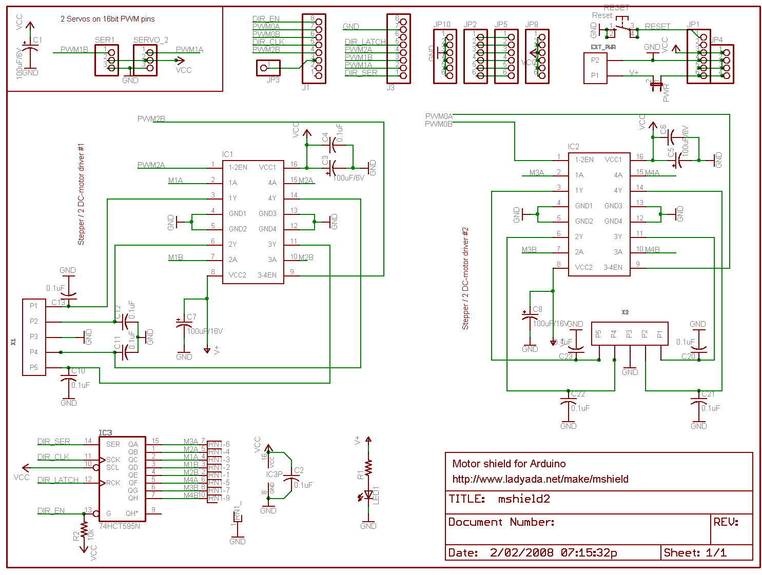
http://www.ladyada.net/images/mshield/mshieldv1-schem.png

Digital pin 2, and 13 are not used.
Digital pin 11: DC Motor #1 / Stepper #1 (activation/speed control)
Digital pin 3: DC Motor #2 / Stepper #1 (activation/speed control)
Digital pin 5: DC Motor #3 / Stepper #2 (activation/speed control)
Digital pin 6: DC Motor #4 / Stepper #2 (activation/speed control)
Digital pin 4, 7, 8 and 12 (and now 13) are used to drive the DC/Stepper motors via the 74HC595 serial-to-parallel latch


OK, now at the end will be the modified library posted, but here is what I did.
Coding wise this may not be the most efficient method because of the redundant libaries, but it made the hack very easy to do w/o risk of messing up the code.


Copy the AFMotor directory in the arduino/libraries directory to AFMotorA.  In the copy, change the names of AFMotor.h and AFMotor.cpp to AFMotorA.h and AFMotorA.cpp.  Note that you will have to restart the Arduino software to see the new library.  


Now find the line in the AFcontrol.h file in the libraries directory
#define MOTOR_LATCH 12
and change it to

#define MOTOR_LATCHA 13

We need to change the function names to differentiate which board they apply to.
In AFMotorA.h  globally replace the text "AFMotor" with "AFMotorA" everywhere it appears.

In AFMotorA.cpp, also globally replace the text "AFMotor" with "AFMotorA" everywhere it appears.
Also replace MOTOR_LATCH with MOTOR_LATCHA everywhere it appears.

Now you have two libraries, which address different boards.  So here is a stepper test program that demos the four motors working:
Example Sketch


// Adafruit Motor shield library
// copyright Adafruit Industries LLC, 2009
// this code is public domain, enjoy!
// modified by tomw to drive 2 shields at once
// This requires a modified library 
// 
//with the second having MOTORLATCH on pin 13, renamed MOTORLATCHA
//and several functions renamed to AFMotorA 

#include <AFMotor.h>
#include <AFMotorA.h>

AF_Stepper motorX(48, 1);
AF_Stepper motorY(48, 2);
AF_StepperA motorZ(48, 1);
AF_StepperA motorA(48, 2);

void setup() {
  Serial.begin(9600);           // set up Serial library at 9600 bps
  Serial.println("Stepper test!");

  motorX.setSpeed(60);  // 60 rpm   
  motorY.setSpeed(60);  // 60 rpm   
  motorZ.setSpeed(60);  // 60 rpm   
  motorA.setSpeed(60);  // 60 rpm  
  
  delay(5000);  // wait for the supply to come up
  
  //step motors one step and back to power the coils
  motorX.step(1, FORWARD, SINGLE); 
  motorY.step(1, FORWARD, SINGLE);
  motorZ.step(1, FORWARD, SINGLE); 
  motorA.step(1, FORWARD, SINGLE);
  motorX.step(1, BACKWARD, SINGLE); 
  motorY.step(1, BACKWARD, SINGLE);
  motorZ.step(1, BACKWARD, SINGLE); 
  motorA.step(1, BACKWARD, SINGLE);
}

void loop() { 
  Serial.println("Single coil steps");
  motorX.step(480, FORWARD, SINGLE); 
  delay(1000);
  motorY.step(480, FORWARD, SINGLE); 
  delay(1000);
  motorZ.step(480, FORWARD, SINGLE); 
  delay(1000);
  motorA.step(480, FORWARD, SINGLE); 
  delay(1000);
  motorX.step(480, BACKWARD, SINGLE); 
  delay(1000);
  motorY.step(480, BACKWARD, SINGLE); 
  delay(1000);
  motorZ.step(480, BACKWARD, SINGLE); 
  delay(1000);
  motorA.step(480, BACKWARD, SINGLE); 
  delay(1000);
 // Now all runing at once!  Bravo!
  int i;
  for (i=0;  i<480; i++) {
    motorX.step(2, FORWARD, SINGLE); 
    motorY.step(1, FORWARD, SINGLE); 
    motorZ.step(2, FORWARD, SINGLE); 
    motorA.step(1, FORWARD, SINGLE); 
  }

}

Modified Libraries follow, AFmotorA.h and AFmotorA.cpp

Saturday, February 26, 2011

Position sensor for Arduino XYZ CNC Carving Machine

This is a sub post of the larger XYZ machine post project.  This piece is about an Arduino based module that reads rotary encoders and displays on an LCD the current machine position;

A couple photos of the breadboard version.  Note the three encoders are under the display, this prototype wasn't really meant to be used for anything.  Of course the permanent version will have the encoders attached to the XYZ machine and not on a breadboard.


This picture (pardon the rotation) shows the display, you can just see one of the encoders on the breadboard below the display.  This picture was taken before I added the math to print out converted inches, it just shows the raw encoder count.


I might also later have at least one button to set the home position, or I may just rely on the Arduino reset button to set 0,0,0.  Some sort of home/limit switch setup might be nice too.


The encoders are attached to the ends of the drive screws for the platform.  I used a short piece of flexible plastic tubing from the hardware store, because I couldn't find set screw shaft couplers the right size for any reasonable price.  The hose gives me a little flex, so it should be OK.  It stretches over the encoder shaft and the drive shaft.


Using rotary encoders from sparkfun. They are inexpensive, I hope they hold up to the job over time.  They are really for human  input knobs. http://www.sparkfun.com/products/9117  
Datasheet: http://www.sparkfun.com/datasheets/Components/TW-700198.pdf
Later I swapped with some slightly different encoders from Digikey 
http://search.digikey.com/scripts/DkSearch/dksus.dll?WT.z_header=search_go&lang=en&site=us&keywords=987-1199-ND&x=20&y=18
http://www.bitechnologies.com/pdfs/en16.pdf
I changed because these didn't have detents, which tended to snap the encoders to certain values.  Also these had threaded shafts and were easier to mount.  For $1.18 why not get the best?


Some example rotary encoder code that I started with is here:
http://www.circuitsathome.com/mcu/reading-rotary-encoder-on-arduino


The example code worked out of the box, I modified it to read three encoders at the same time. 
It makes use of port manipulation to read all the input simultaneously.  This page helped http://www.arduino.cc/en/Reference/PortManipulation
However, this guy must have been a programmer for a living, the program was basically 2 lines and very hard to understand.   I wrote my version with more comments and a little less pizazz.  Hopefully more understandable.


Got the three encoder code working, included it below, it was a bit tricky.   


I added the LCD readout, attempting to keep the code delays as small as possible so we don't skip and encoder positions.  The LCD is hooked up pretty much like all the Arduino examples, using 4 bit wide parallel mode.  I like to use pins 7 6 5 4 3 2 because it keeps all the LCD pins on the same Arduino connector.   You might note in the photo there is a adafruit arduino prototype board and some headers that I use to stack the LCD on top of the Arduino and map the pins.   I'm not going to repeat the LCD interfacing stuff in this post.   The Optrex display i used is cost effective but a bit quirky, it has the tendency to print garbage if you give it commands too fast.


The code is after the break:

Monday, February 21, 2011

Arduino based "crazy clock" idea

I thought of something fun to do with them, to make an analog crazy clock or backwards clock.
I have some small stepper motors from adafruit.
The arduino could keep time, and drive the steppers to move the hands in any pattern you want.
This could mimic a watch I've seen where the hours are out of order.
http://www.blogcdn.com/www.luxist.com/media/2009/05/franck-muller-crazy-hours-watch-blue.jpg

Just writing it down to come back to it later if I get bored

Sunday, February 20, 2011

Replaced the windshield washer nozzle in a 04 Sienna minivan

Ice and snow broke off the black plastic washer nozzle on the hood of my minivan.   Activating the windshield washer resulted in a fountain of spray straight up, no where near the window.  Here on the east coast, you lose your windshield washer, it is pretty much not safe to drive your car in the winter.

Looked all over the internet, and found it is really hard to buy a replacement.  None of the online auto part stores, ebay or amazon had it.   Some cars are there, but not mine.  Had to resort to going physically to the dealer and buying it.  Yuck.  But the Toyota dealer had it.

Fun part is, you open the hood and it is very tough to access the nozzle.  They have press in ears that clip them in place.  Under the hood is an insulation layer of fabric that has press in clips.  Removing it looked like a very bad idea, the clips were going to break and the fabric tear.  I pried up one edge and could sneak my hand under.  Felt around and couldn't access the back of the washer still to free it up because of the metal.

Found an easy way to do it from outside the car, that worked great.  Grabbed what remained of the nozzle with some pliers and crushed it.  That left the base in the hole, and I was able to use a small screw driver to release the clips from the top of the hood and pull it up out of the top of the hood with the hose still attached.  Pulled off the hose from the old nozzle, and put the new one on the hose.  Snapped the new nozzle into the hole and Voila!.  Took less than 5 minutes this way!

Monday, February 14, 2011

Arduino LCD Countdown Clock

Quickie project for a desktop clock that counts down to when my work project has to be done, then counts how many weeks it is late.


The design is the "raw electronics" look.  The arduino is mounted on the back of the large LCD display by nothing more than a stacked header, and hot glued to a small piece of wood for a base.

The code is built on top of the basic example for a clock that syncs from the PC, found here:
The Arduino Time Library on the Arduino Playground
http://www.arduino.cc/playground/Code/Time

When plugged into the PC and using the Arduino serial monitor, it waits for you to enter a unix timestamp.
You can generate these from web sites like these ones:
http://www.timestampgenerator.com/
http://www.unixtimestamp.com/index.php

They have the form of seconds since Jan 01 1970, type in T1297687386
Type that in the start the clock.  There are PC programs out there that run a host to send that string, like gobetwino if you want to do that to, you don't need to.  This is just a manual start.

Change this variable in the code to the unix timestamp of the event you want to count down to
signed long tapeout = 1309539600;

The hardware is nothing more than an arduino interfaced to a huge 20x4 backlit LCD module, using the 4 bit wide parallel communication mode.  The pinout is a very slight mod to the descriptions in the Arduino examples, because I like to group the pins all on one header.   This is exactly like the setup in the Arduino examples.

I use an external wall wart as power, so it doesn't have to be plugged into the PC all the time.

Here is the code


* Sketch for 4x20 LCD to display current time and date, and countdown of weeks, days, hours, min to an event
 *
 */

#include <Time.h>
#include <LiquidCrystal.h>
LiquidCrystal lcd(7, 6 , 5, 4, 3, 2);

#define TIME_MSG_LEN  11   // time sync to PC is HEADER followed by unix time_t as ten ascii digits
#define TIME_HEADER  'T'   // Header tag for serial time sync message
#define TIME_REQUEST  7    // ASCII bell character requests a time sync message

signed long tapeout = 1309539600;

// to make sure the display is cleared once a day
int yesterday = 0;
int weeksleft = 0;
int daysleft = 0;
int hoursleft = 0;
int minleft = 0;


void setup()  {
  lcd.begin(20, 4);
  lcd.clear();
  //backlight on pin 8
  pinMode(8, OUTPUT);
  digitalWrite(8, LOW);
  Serial.begin(9600);
  setSyncProvider( requestSync);  //set function to call when sync required
  Serial.println("Waiting for sync message");
  Serial.println("Unix Timestamp");
  Serial.println("Example T1297674000");
  lcd.setCursor(0,0);
  lcd.print("Waiting for PC time sync...");
}

void loop(){  
  if(Serial.available() )
  {
    processSyncMessage();
    digitalWrite(8, HIGH);
  }
  if(timeStatus()!= timeNotSet)
  {
    digitalClockDisplay();
  
    // clear the display if the day changes to clear glitches
    if (day() != yesterday) {
        //lcd.clear();
        yesterday = day();
    }
  }
  delay(20000);  //can be set to 1000, this makes the display more stable
}

void digitalClockDisplay(){

  //turn on backlight only during workday
  if((hour() >= 8) & (hour() < 19)) digitalWrite(8, HIGH);
  else   digitalWrite(8, LOW);

  // digital clock display of the time
  lcd.setCursor(0,0);
  Serial.print(hour());
  lcd.print(hourFormat12());
  printDigits(minute());
  //printDigits(second());
  Serial.print("   ");
  if (isAM()) lcd.print(" AM ");
  if (isPM()) lcd.print(" PM ");
  Serial.print(dayStr(weekday()));
  lcd.print(dayStr(weekday()));
  Serial.print(" ");
  lcd.print(" ");
  lcd.setCursor(0,1);
  Serial.print(day());
  lcd.print(day());
  Serial.print(" ");
    lcd.print(" ");
  Serial.print(monthShortStr(month()));
    lcd.print(monthShortStr(month()));
  Serial.print(" ");
    lcd.print(" ");
  Serial.print(year());
    lcd.print(year());
  Serial.println();
  lcd.setCursor(0,2);
  if (tapeout < now()) {
      weeksleft = (now() - tapeout)/60/60/24/7;
      daysleft = (now() - tapeout)/60/60/24 - weeksleft*7;
      hoursleft = (now() - tapeout)/60/60 - daysleft*24 - weeksleft*7*24;
      minleft =  (now() - tapeout)/60 - hoursleft*60 - daysleft*24*60 - weeksleft*7*24*60;
      lcd.print(   weeksleft   );
      lcd.print("wk ");
      lcd.print(   daysleft   );
      lcd.print("d ");
      lcd.print(   hoursleft   );
      lcd.print("h ");
      lcd.print(   minleft  );
      lcd.print("m ");
      lcd.setCursor(0,3);
      lcd.print("Late! OMG! Ship It!   ");
  } else {
      weeksleft = (tapeout - now())/60/60/24/7;
      daysleft = (tapeout - now())/60/60/24 - weeksleft*7 ;
      hoursleft = (tapeout - now())/60/60 - daysleft*24 - weeksleft*7*24;
      minleft =  (tapeout - now())/60 - hoursleft*60 - daysleft*24*60 - weeksleft*7*24*60;
      lcd.print(   weeksleft   );
      lcd.print("wk ");
      lcd.print(   daysleft   );
      lcd.print("d ");
      lcd.print(   hoursleft   );
      lcd.print("h ");
      lcd.print(   minleft  );
      lcd.print("m  ");
      lcd.setCursor(0,3);
      lcd.print("To Santan Tapeout! ");
  }
}

void printDigits(int digits){
  // utility function for digital clock display: prints preceding colon and leading 0
  Serial.print(":");
  lcd.print(":");
  if(digits < 10){
    Serial.print('0');
    lcd.print('0');
  }
  Serial.print(digits);
  lcd.print(digits);
}

void processSyncMessage() {
  lcd.clear();
  // if time sync available from serial port, update time and return true
  while(Serial.available() >=  TIME_MSG_LEN ){  // time message consists of a header and ten ascii digits
    char c = Serial.read() ;
    Serial.print(c);
    if( c == TIME_HEADER ) {    
      time_t pctime = 0;
      for(int i=0; i < TIME_MSG_LEN -1; i++){
        c = Serial.read();        
        if( c >= '0' && c <= '9'){
          pctime = (10 * pctime) + (c - '0') ; // convert digits to a number  
        }
      }
      setTime(pctime);   // Sync Arduino clock to the time received on the serial port
    }
  }
}

time_t requestSync()
{
  Serial.print(TIME_REQUEST,BYTE);
  return 0; // the time will be sent later in response to serial mesg
}


Saturday, January 29, 2011

Replaced the laser in a Wii

My son's Wii was throwing out "The disc could not be read" or "System error, please consult your manual" constantly.  Most games were unplayable.  We tried cleaning, to no avail.  This happens more on "Super Smash Brothers" and some other games because they use the double layer discs and demand more of the laser.  Eventually it will happen on every disc.

This happens because the lasers used for reading discs age.  They get weaker and weaker the longer they are used.  Eventually they are too dim to work.

This repair is not for everyone. It takes a Nintendo triwing screwdriver and a jewelers Philips head screwdriver set, small pliers, soldering iron and I use a magnifying lamp (but I'm old).   If you are fairly mechanically inclined, careful keeping track of the screws, cables, etc. You can do it.  It took me about two hours and I do this kind of stuff all the time.  If this is your first it will probably take a lot longer.  Otherwise go for buying a replacement drive, they cost 60 bucks and up, but you avoid the tricky parts of the repair, the soldering, and almost all the ribbon cables.

This Wii was one of the original Wii's, we bought it in November 2006 for Christmas, stood in line and everything.  He plays it constantly, and leaves it on all the time.  We had already sent it back to Nintendo once for this problem when it was under warranty and they repaired it.   I recommend if your Wii is fairly new to go this route.  Nintendo is one of the better companies out there for repairing stuff for free, even if it is marginally your fault or a little too long.  He didn't want to have a new one, because of all the saved games and downloads on this console.  We had to fix this one and I'm cheap and adventurous!

Bought this part on Amazon.  It comes with no instructions, and very sketchy details on the description as to what it does or how to use it.  No worries!

Brand New Laser Lens for Wii Replacement Part


It did come with the Nintendo screwdriver.

The Wii is much more challenging to open than other consoles and even the Gamecube.   There are screws hidden everywhere, under stickers, rubber feet etc.  Take you time and find them all.  Several guides are out on the web like this one:
http://dodisdodat.com/tutorials/repair-guides/100-fix-it-yourself-how-to-open-a-wii.html
This will get the covers off.

The DVD drive has four screws the remove it, two that are obvious and two that you access through holes in the drive near where the disc goes in.  They are silver and hold the black plastic down.   I admit I unnecessarily took the top cover off the DVD drive, where the disk sits.  That meant removing extra screws and risking messing up the plastic gear assemblies in the drive.  Don't do this, the laser is not there.  Only remove the DVD hold down screws, the laser is on the bottom of the drive.

When you lift the drive there are several ribbon cables that you have to remove.  Some plug in, others have tiny clamps on the board that you have to slide back or flip up.  This is classic Nintendo construction.  The ribbons look much more fragile than they are, but still be careful.

To remove the laser from the drive, you have to take the circuit board up by removing some screws, and then a couple more ribbon connectors.   Then there is a sheet metal cover that you have to pry off.  It has four clips on each side.  It was very difficult to get off, the best way is to stick a screwdriver in from the other side.

Finally you can see the laser.  You remove the two screws near the edge that appear to do nothing.  They allow you to slide the sliver rails that the laser moves on out of the edge of the case.  Take the old laser out, transfer the white plastic triangle that engages the gear from the old laser to the new.  Slide it on the rails and push the rails back in.  

Note!  There is a tiny solder blob on the ribbon cable of the laser.  This is protection from electrostatic damage.  You will see in the old laser that this blob is divided.  You need to use a soldering iron to heat this blob and flick it off.  Otherwise the laser will not work.

Whew. I tested it after putting back together a few screws and the ribbon cables.  There was one glitch.  The drive thought there was a disc in it, mostly because i had taken it apart (see above) when I didn't have to.  Couldn't put a disc in.  However, pressing eject fixed the problem.  A few extra clicks and odd noises and everything snapped back into place.  Tried it with a regular CD as the sacrificial lamb, and it went in and out just fine.  Time to try a real game.  Bingo!  It reads the disks.  Played some games.  Awesome!

OK, now put it all back together.

This is great for your ego, I recommend it to everyone.   Makes you a hero to kids who will be asking if you are sure you know what you are doing the whole time.