Search This Blog

Sunday, March 6, 2011

Arduino based XYZ CNC Carving Machine

Starting a new thread now that I have a plan....

THE PLAN

After some poking around researching building a small CNC machine for light carving, I came to the conclusion that the Zen toolworks CNC machine was a good deal and would shave months off my project.   I figured by the time I collected steppers, lead screws, made parts etc I'd spend a more than this and get a worse result.   This kit is the stage, leadscrews and steppers.  No electronics/drivers are included.  It is fairly small but it looks like a great leg up.

Here is what I'm planning to use

Zen Toolworks CNC Carving Machine DIY Kit 7x7. 


My initial plan is to use Arduinos as the motor controllers.  I like the older Arduino, because it is a tad cheaper, and really functionally equivalent to the Uno.  Amazon for the free shipping and no tax.

Arduino Duemilanove

http://www.amazon.com/gp/product/B004A7L3NC/ref=as_li_qf_sp_asin_il_tl?ie=UTF8&tag=workingsilico-20&linkCode=as2&camp=1789&creative=9325&creativeASIN=B004A7L3NC


Most CNC software uses a computer parallel port to synchronize output bits to control the motor, and perhaps the Arduino isn't really the best solution.  However parallel ports are old and obsolete, so I'm going to make my own controller anyway.  Irrational decision probably, but buying an old parallel port board makes me nauseous.    If i can control all the motors from one Arduino, I can keep the synchronization with no work.
Motor driver controllers are way expensive and even with a coulple Arduinos and motor control boards, I'm probably coming out ahead.

Bought two motor control boards from adafruit.  A prebuilt board that saves a lot of time, from an A+ vendor.

Adafruit Motor/Stepper/Servo Shield for Arduino kit - v1.0

http://www.adafruit.com/index.php?main_page=product_info&cPath=17_21&products_id=81

I want to be able to know the position of the machine at all times.  This isn't really needed for stepper motor controlled machines, don't need feedback.   However for manual stepping and testing, I wanted a readout.
Will try to read back position via cheap rotary encoders, 
http://www.sparkfun.com/products/9117
I may just use the encoders for calibration, or monitoring.  A feedback loop solution may be overkill.  It depends on the torque and backlash of the motors.  TBD.

The arduinos will commnicate via USB to the host PC.
The software is a journey, but there is tons of stuff on the web, so we will see!


DRIVING THE MOTORS

The stepper is rated for 1.68A at 2.8V.  I'm going to have to run it at 5V, because the driver chips need at least 4.5V, and I'm using a repurposed ATX computer power supply to give me 5V.
The stepper that comes with the Zen is this one:
http://www.savebase.com/InfoBase/SAVEBASE/PKG/001520/Image/nema17%20copy.jpg
42BYGH47-401A
I understand that it can take the higher voltage, but the current will go up.  Have to be careful to not step too fast since I don't have a current limiter.  Maybe I could put a 1.3 ohm resistor in series to limit the current to 1.68A.  It would have to be a 3.6W resistor.  They are available as wirewounds for >$1.  That would add inductance for sure.  I will wait and see how it works first.
Upgraded the L293D drivers with SN754410 in the adafruit stepper motor board, it wasn't driving the stepper very well.  They are pin for pin compatible.  I will solder two together to get 2A.  Three might be even safer.  Added a heat sink too.  http://www.aavidthermalloy.com/cgi-bin/stdisp_print.pl?Pnum=580200b00000g.  Bought this at digikey.com.

Stacking the two driver chips turned out to be tricky, and after making a big solder short, and apparently ruining one driver chip, i found the method to do this.   Solder the two chips piggy back BEFORE you put them onto the pc board.  Put one in a vice, piggyback the second, then solder tack the end pins on both sides.  Then come back and one by one solder the pins together.   Then put the assembly into the PC board.

To use a computer power supply, you have to trick it to turn on like this guy shows:
http://www.youtube.com/watch?v=rivoVzxwNtI
After that, just use any of the red and black wires.  Says it will source 32A.  wow.

Set it up, used a scrounged PC power connector to plug it in, shorted the two pins as described and 5.1V, cool and quiet.  Plugged it into the stepper motor board and the Zen toolworks steppers, and it is working great.  The chips do get a bit hot, so i'm thankful for the heat sink and I'm suing the power supply fan to blow across the driver boards.

In this photo you can see the power supply, the Arduino with the motor control board on top, the double stacked driver chips and heat sinks, connected to the stepper motors.


Then i moved on and modified the Adafruit motor shield so that I could stack two shields on top of each other and control 4 motors at once (only have three right now).  Made a stand alone post for what I did here, it was so cool.   Basically a small hack to give each board it's own latch pin.  Only took one more pin to differentiate which board responds to the commands to the motors, and the other motors still hold their value.  Awesome!
http://blog.workingsi.com/2011/03/method-for-controlling-4-steppers-from.html
Arduino with two Adafruit motor shields on top, connected to the PC 5V power supply and three motors (3rd is out of the picture)

READING THE ENCODERS

Now I need to build an Arduino module with the rotary encoders and an LCD display to show the position. I will also have at least one button to set the home position.
Back to the rotary encoders from sparkfun. Some sample code is here:
http://www.circuitsathome.com/mcu/reading-rotary-encoder-on-arduino
Datasheet: http://www.sparkfun.com/datasheets/Components/TW-700198.pdf
The sample code worked out of the box, now to modify it to read three encoders.
It makes use of port manipulation to read all the input simultaneously.  This page helped http://www.arduino.cc/en/Reference/PortManipulation
Got the three encoder code working, I made a separate post for it so I could include it in the blog, look for it.
http://blog.workingsi.com/2011/02/position-sensor-for-arduino-xyz-cnc.html
I rewrote the code so it made sense to me, the example took a lot of head scratching.


Attached the three encoders to the machine temporarily, and it is working great.  Stepped over and back and it returns to the same position.  No worries about he rotary encoders missing steps.

LIMIT SWITCHES
found some small limit switches for <$2 a piece.  The plan is to use them to interrupt the jumper wire on the PC power supply, thereby killing power if the stage is going to hit the walls.   I was advised by a friend that it can be a pain to unstick yourself if you have killed the motor power, but I will turn the stage back by hand if this happens.
http://www.amazon.com/gp/product/B002P4XQY6/ref=as_li_qf_sp_asin_il_tl?ie=UTF8&tag=workingsilico-20&linkCode=as2&camp=1789&creative=9325&creativeASIN=B002P4XQY6

WRITING THE CODE

Now I have moved on to coding.   Plan is to write or borrow a simple Gcode interpreter than can run on the Arduino.   I found this page, making a note:
http://dank.bengler.no/-/page/show/5470_grbl?ref=mst

I hope to be able to use some open source software for the graphics.  Looks like the defacto is EMC2.  EMC2 is open source CNC software at http://www.linuxcnc.org/content/view/11/10/lang,en/.  I will have to use Linux ubuntu for this, but since it probably would be best to use a dedicated PC, Linux is a good choice because I can use an old PC knocking about.  Had hoped to use windows to be able to make visual basic widgets.  I'll come back to that later.   I may need to write some layer of code between the serial ports and the EMC2, since it wants to drive a parallel port and do all the thinking.  "G-code" is the format for the commands that EMC2 produces.

Found this link, he beat me to it!  Arduino controlling and translating Gcode.
http://code.google.com/p/rsteppercontroller/

I decided to start some new posts for the coding, so look there for updates

Thursday, March 3, 2011

Method for controlling 4 steppers from Arduino and two Motor Shields from Adafruit

This is so I can control the X Y and Z axis stepper motors of a CNC from one single arduino and can avoid a synchronized communication network and multiple Arduinos.  The fourth motor control will be reserved for tool adjustments if needed, it is extra for now.

I wanted to be able to allow all the motors to hold while others were running.  This hack succeeded in getting me 4 motors with full control.  I'm not attempting to microstep, I'm just using this for single stepping, I think maybe the way the library deals with microstepping it may not work because the PWM leads are shared.

Using two of these motor control boards:
http://www.adafruit.com/index.php?main_page=product_info&cPath=17_21&products_id=81

We are going to stack two motor shields on top of the Arduino.  Using stacking headers on the first instead of the headers that come with it.  Got the headers from Adafruit too.    http://www.adafruit.com/index.php?main_page=product_info&cPath=17_21&products_id=85 .   I used two sets of stacking headers because in order to drive my steppers I stacked another set of H bridge drivers on top and used a small 16pin dip heat sink from digikey.

So here comes the very subtle and elegant hack!
On top motor shield, cut pin 12 out of the header pins so it doesn't connect to the top board.  Short pin 12 and 13 on the top motor shield, because pin 13 is the new motor latch for the top shield, and needs to connect to the shield where 12 used to.   A nip and a solder blob and Bob's your uncle.


With the stack, one board will use the latch on pin 12, and the other on pin 13.
All the commands are sent to both, one board ignores (never latches) the commands for the other.  Picked pin 13 for the new latch because it is in the same register as 12 and will be clocked the same way by the port writes.   I don't think this technique is extensible to more boards, because there are no more pins.  pin3 and the analog pins are in different ports and wouldn't be synchronous.

Here you can see the Arduino with two motor shields on top, connected to stepper motors.  The third is out of the picture.   Motor power comes from an old computer ATX power supply 5V.

Some links to facts on the motor shield board:
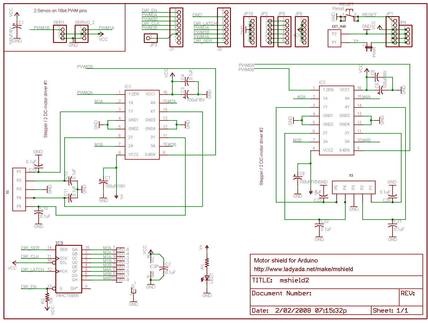
http://www.ladyada.net/images/mshield/mshieldv1-schem.png

Digital pin 2, and 13 are not used.
Digital pin 11: DC Motor #1 / Stepper #1 (activation/speed control)
Digital pin 3: DC Motor #2 / Stepper #1 (activation/speed control)
Digital pin 5: DC Motor #3 / Stepper #2 (activation/speed control)
Digital pin 6: DC Motor #4 / Stepper #2 (activation/speed control)
Digital pin 4, 7, 8 and 12 (and now 13) are used to drive the DC/Stepper motors via the 74HC595 serial-to-parallel latch


OK, now at the end will be the modified library posted, but here is what I did.
Coding wise this may not be the most efficient method because of the redundant libaries, but it made the hack very easy to do w/o risk of messing up the code.


Copy the AFMotor directory in the arduino/libraries directory to AFMotorA.  In the copy, change the names of AFMotor.h and AFMotor.cpp to AFMotorA.h and AFMotorA.cpp.  Note that you will have to restart the Arduino software to see the new library.  


Now find the line in the AFcontrol.h file in the libraries directory
#define MOTOR_LATCH 12
and change it to

#define MOTOR_LATCHA 13

We need to change the function names to differentiate which board they apply to.
In AFMotorA.h  globally replace the text "AFMotor" with "AFMotorA" everywhere it appears.

In AFMotorA.cpp, also globally replace the text "AFMotor" with "AFMotorA" everywhere it appears.
Also replace MOTOR_LATCH with MOTOR_LATCHA everywhere it appears.

Now you have two libraries, which address different boards.  So here is a stepper test program that demos the four motors working:
Example Sketch


// Adafruit Motor shield library
// copyright Adafruit Industries LLC, 2009
// this code is public domain, enjoy!
// modified by tomw to drive 2 shields at once
// This requires a modified library 
// 
//with the second having MOTORLATCH on pin 13, renamed MOTORLATCHA
//and several functions renamed to AFMotorA 

#include <AFMotor.h>
#include <AFMotorA.h>

AF_Stepper motorX(48, 1);
AF_Stepper motorY(48, 2);
AF_StepperA motorZ(48, 1);
AF_StepperA motorA(48, 2);

void setup() {
  Serial.begin(9600);           // set up Serial library at 9600 bps
  Serial.println("Stepper test!");

  motorX.setSpeed(60);  // 60 rpm   
  motorY.setSpeed(60);  // 60 rpm   
  motorZ.setSpeed(60);  // 60 rpm   
  motorA.setSpeed(60);  // 60 rpm  
  
  delay(5000);  // wait for the supply to come up
  
  //step motors one step and back to power the coils
  motorX.step(1, FORWARD, SINGLE); 
  motorY.step(1, FORWARD, SINGLE);
  motorZ.step(1, FORWARD, SINGLE); 
  motorA.step(1, FORWARD, SINGLE);
  motorX.step(1, BACKWARD, SINGLE); 
  motorY.step(1, BACKWARD, SINGLE);
  motorZ.step(1, BACKWARD, SINGLE); 
  motorA.step(1, BACKWARD, SINGLE);
}

void loop() { 
  Serial.println("Single coil steps");
  motorX.step(480, FORWARD, SINGLE); 
  delay(1000);
  motorY.step(480, FORWARD, SINGLE); 
  delay(1000);
  motorZ.step(480, FORWARD, SINGLE); 
  delay(1000);
  motorA.step(480, FORWARD, SINGLE); 
  delay(1000);
  motorX.step(480, BACKWARD, SINGLE); 
  delay(1000);
  motorY.step(480, BACKWARD, SINGLE); 
  delay(1000);
  motorZ.step(480, BACKWARD, SINGLE); 
  delay(1000);
  motorA.step(480, BACKWARD, SINGLE); 
  delay(1000);
 // Now all runing at once!  Bravo!
  int i;
  for (i=0;  i<480; i++) {
    motorX.step(2, FORWARD, SINGLE); 
    motorY.step(1, FORWARD, SINGLE); 
    motorZ.step(2, FORWARD, SINGLE); 
    motorA.step(1, FORWARD, SINGLE); 
  }

}

Modified Libraries follow, AFmotorA.h and AFmotorA.cpp

Saturday, February 26, 2011

Position sensor for Arduino XYZ CNC Carving Machine

This is a sub post of the larger XYZ machine post project.  This piece is about an Arduino based module that reads rotary encoders and displays on an LCD the current machine position;

A couple photos of the breadboard version.  Note the three encoders are under the display, this prototype wasn't really meant to be used for anything.  Of course the permanent version will have the encoders attached to the XYZ machine and not on a breadboard.


This picture (pardon the rotation) shows the display, you can just see one of the encoders on the breadboard below the display.  This picture was taken before I added the math to print out converted inches, it just shows the raw encoder count.


I might also later have at least one button to set the home position, or I may just rely on the Arduino reset button to set 0,0,0.  Some sort of home/limit switch setup might be nice too.


The encoders are attached to the ends of the drive screws for the platform.  I used a short piece of flexible plastic tubing from the hardware store, because I couldn't find set screw shaft couplers the right size for any reasonable price.  The hose gives me a little flex, so it should be OK.  It stretches over the encoder shaft and the drive shaft.


Using rotary encoders from sparkfun. They are inexpensive, I hope they hold up to the job over time.  They are really for human  input knobs. http://www.sparkfun.com/products/9117  
Datasheet: http://www.sparkfun.com/datasheets/Components/TW-700198.pdf
Later I swapped with some slightly different encoders from Digikey 
http://search.digikey.com/scripts/DkSearch/dksus.dll?WT.z_header=search_go&lang=en&site=us&keywords=987-1199-ND&x=20&y=18
http://www.bitechnologies.com/pdfs/en16.pdf
I changed because these didn't have detents, which tended to snap the encoders to certain values.  Also these had threaded shafts and were easier to mount.  For $1.18 why not get the best?


Some example rotary encoder code that I started with is here:
http://www.circuitsathome.com/mcu/reading-rotary-encoder-on-arduino


The example code worked out of the box, I modified it to read three encoders at the same time. 
It makes use of port manipulation to read all the input simultaneously.  This page helped http://www.arduino.cc/en/Reference/PortManipulation
However, this guy must have been a programmer for a living, the program was basically 2 lines and very hard to understand.   I wrote my version with more comments and a little less pizazz.  Hopefully more understandable.


Got the three encoder code working, included it below, it was a bit tricky.   


I added the LCD readout, attempting to keep the code delays as small as possible so we don't skip and encoder positions.  The LCD is hooked up pretty much like all the Arduino examples, using 4 bit wide parallel mode.  I like to use pins 7 6 5 4 3 2 because it keeps all the LCD pins on the same Arduino connector.   You might note in the photo there is a adafruit arduino prototype board and some headers that I use to stack the LCD on top of the Arduino and map the pins.   I'm not going to repeat the LCD interfacing stuff in this post.   The Optrex display i used is cost effective but a bit quirky, it has the tendency to print garbage if you give it commands too fast.


The code is after the break:

Monday, February 21, 2011

Arduino based "crazy clock" idea

I thought of something fun to do with them, to make an analog crazy clock or backwards clock.
I have some small stepper motors from adafruit.
The arduino could keep time, and drive the steppers to move the hands in any pattern you want.
This could mimic a watch I've seen where the hours are out of order.
http://www.blogcdn.com/www.luxist.com/media/2009/05/franck-muller-crazy-hours-watch-blue.jpg

Just writing it down to come back to it later if I get bored

Sunday, February 20, 2011

Replaced the windshield washer nozzle in a 04 Sienna minivan

Ice and snow broke off the black plastic washer nozzle on the hood of my minivan.   Activating the windshield washer resulted in a fountain of spray straight up, no where near the window.  Here on the east coast, you lose your windshield washer, it is pretty much not safe to drive your car in the winter.

Looked all over the internet, and found it is really hard to buy a replacement.  None of the online auto part stores, ebay or amazon had it.   Some cars are there, but not mine.  Had to resort to going physically to the dealer and buying it.  Yuck.  But the Toyota dealer had it.

Fun part is, you open the hood and it is very tough to access the nozzle.  They have press in ears that clip them in place.  Under the hood is an insulation layer of fabric that has press in clips.  Removing it looked like a very bad idea, the clips were going to break and the fabric tear.  I pried up one edge and could sneak my hand under.  Felt around and couldn't access the back of the washer still to free it up because of the metal.

Found an easy way to do it from outside the car, that worked great.  Grabbed what remained of the nozzle with some pliers and crushed it.  That left the base in the hole, and I was able to use a small screw driver to release the clips from the top of the hood and pull it up out of the top of the hood with the hose still attached.  Pulled off the hose from the old nozzle, and put the new one on the hose.  Snapped the new nozzle into the hole and Voila!.  Took less than 5 minutes this way!

Monday, February 14, 2011

Arduino LCD Countdown Clock

Quickie project for a desktop clock that counts down to when my work project has to be done, then counts how many weeks it is late.


The design is the "raw electronics" look.  The arduino is mounted on the back of the large LCD display by nothing more than a stacked header, and hot glued to a small piece of wood for a base.

The code is built on top of the basic example for a clock that syncs from the PC, found here:
The Arduino Time Library on the Arduino Playground
http://www.arduino.cc/playground/Code/Time

When plugged into the PC and using the Arduino serial monitor, it waits for you to enter a unix timestamp.
You can generate these from web sites like these ones:
http://www.timestampgenerator.com/
http://www.unixtimestamp.com/index.php

They have the form of seconds since Jan 01 1970, type in T1297687386
Type that in the start the clock.  There are PC programs out there that run a host to send that string, like gobetwino if you want to do that to, you don't need to.  This is just a manual start.

Change this variable in the code to the unix timestamp of the event you want to count down to
signed long tapeout = 1309539600;

The hardware is nothing more than an arduino interfaced to a huge 20x4 backlit LCD module, using the 4 bit wide parallel communication mode.  The pinout is a very slight mod to the descriptions in the Arduino examples, because I like to group the pins all on one header.   This is exactly like the setup in the Arduino examples.

I use an external wall wart as power, so it doesn't have to be plugged into the PC all the time.

Here is the code


* Sketch for 4x20 LCD to display current time and date, and countdown of weeks, days, hours, min to an event
 *
 */

#include <Time.h>
#include <LiquidCrystal.h>
LiquidCrystal lcd(7, 6 , 5, 4, 3, 2);

#define TIME_MSG_LEN  11   // time sync to PC is HEADER followed by unix time_t as ten ascii digits
#define TIME_HEADER  'T'   // Header tag for serial time sync message
#define TIME_REQUEST  7    // ASCII bell character requests a time sync message

signed long tapeout = 1309539600;

// to make sure the display is cleared once a day
int yesterday = 0;
int weeksleft = 0;
int daysleft = 0;
int hoursleft = 0;
int minleft = 0;


void setup()  {
  lcd.begin(20, 4);
  lcd.clear();
  //backlight on pin 8
  pinMode(8, OUTPUT);
  digitalWrite(8, LOW);
  Serial.begin(9600);
  setSyncProvider( requestSync);  //set function to call when sync required
  Serial.println("Waiting for sync message");
  Serial.println("Unix Timestamp");
  Serial.println("Example T1297674000");
  lcd.setCursor(0,0);
  lcd.print("Waiting for PC time sync...");
}

void loop(){  
  if(Serial.available() )
  {
    processSyncMessage();
    digitalWrite(8, HIGH);
  }
  if(timeStatus()!= timeNotSet)
  {
    digitalClockDisplay();
  
    // clear the display if the day changes to clear glitches
    if (day() != yesterday) {
        //lcd.clear();
        yesterday = day();
    }
  }
  delay(20000);  //can be set to 1000, this makes the display more stable
}

void digitalClockDisplay(){

  //turn on backlight only during workday
  if((hour() >= 8) & (hour() < 19)) digitalWrite(8, HIGH);
  else   digitalWrite(8, LOW);

  // digital clock display of the time
  lcd.setCursor(0,0);
  Serial.print(hour());
  lcd.print(hourFormat12());
  printDigits(minute());
  //printDigits(second());
  Serial.print("   ");
  if (isAM()) lcd.print(" AM ");
  if (isPM()) lcd.print(" PM ");
  Serial.print(dayStr(weekday()));
  lcd.print(dayStr(weekday()));
  Serial.print(" ");
  lcd.print(" ");
  lcd.setCursor(0,1);
  Serial.print(day());
  lcd.print(day());
  Serial.print(" ");
    lcd.print(" ");
  Serial.print(monthShortStr(month()));
    lcd.print(monthShortStr(month()));
  Serial.print(" ");
    lcd.print(" ");
  Serial.print(year());
    lcd.print(year());
  Serial.println();
  lcd.setCursor(0,2);
  if (tapeout < now()) {
      weeksleft = (now() - tapeout)/60/60/24/7;
      daysleft = (now() - tapeout)/60/60/24 - weeksleft*7;
      hoursleft = (now() - tapeout)/60/60 - daysleft*24 - weeksleft*7*24;
      minleft =  (now() - tapeout)/60 - hoursleft*60 - daysleft*24*60 - weeksleft*7*24*60;
      lcd.print(   weeksleft   );
      lcd.print("wk ");
      lcd.print(   daysleft   );
      lcd.print("d ");
      lcd.print(   hoursleft   );
      lcd.print("h ");
      lcd.print(   minleft  );
      lcd.print("m ");
      lcd.setCursor(0,3);
      lcd.print("Late! OMG! Ship It!   ");
  } else {
      weeksleft = (tapeout - now())/60/60/24/7;
      daysleft = (tapeout - now())/60/60/24 - weeksleft*7 ;
      hoursleft = (tapeout - now())/60/60 - daysleft*24 - weeksleft*7*24;
      minleft =  (tapeout - now())/60 - hoursleft*60 - daysleft*24*60 - weeksleft*7*24*60;
      lcd.print(   weeksleft   );
      lcd.print("wk ");
      lcd.print(   daysleft   );
      lcd.print("d ");
      lcd.print(   hoursleft   );
      lcd.print("h ");
      lcd.print(   minleft  );
      lcd.print("m  ");
      lcd.setCursor(0,3);
      lcd.print("To Santan Tapeout! ");
  }
}

void printDigits(int digits){
  // utility function for digital clock display: prints preceding colon and leading 0
  Serial.print(":");
  lcd.print(":");
  if(digits < 10){
    Serial.print('0');
    lcd.print('0');
  }
  Serial.print(digits);
  lcd.print(digits);
}

void processSyncMessage() {
  lcd.clear();
  // if time sync available from serial port, update time and return true
  while(Serial.available() >=  TIME_MSG_LEN ){  // time message consists of a header and ten ascii digits
    char c = Serial.read() ;
    Serial.print(c);
    if( c == TIME_HEADER ) {    
      time_t pctime = 0;
      for(int i=0; i < TIME_MSG_LEN -1; i++){
        c = Serial.read();        
        if( c >= '0' && c <= '9'){
          pctime = (10 * pctime) + (c - '0') ; // convert digits to a number  
        }
      }
      setTime(pctime);   // Sync Arduino clock to the time received on the serial port
    }
  }
}

time_t requestSync()
{
  Serial.print(TIME_REQUEST,BYTE);
  return 0; // the time will be sent later in response to serial mesg
}


Saturday, January 29, 2011

Replaced the laser in a Wii

My son's Wii was throwing out "The disc could not be read" or "System error, please consult your manual" constantly.  Most games were unplayable.  We tried cleaning, to no avail.  This happens more on "Super Smash Brothers" and some other games because they use the double layer discs and demand more of the laser.  Eventually it will happen on every disc.

This happens because the lasers used for reading discs age.  They get weaker and weaker the longer they are used.  Eventually they are too dim to work.

This repair is not for everyone. It takes a Nintendo triwing screwdriver and a jewelers Philips head screwdriver set, small pliers, soldering iron and I use a magnifying lamp (but I'm old).   If you are fairly mechanically inclined, careful keeping track of the screws, cables, etc. You can do it.  It took me about two hours and I do this kind of stuff all the time.  If this is your first it will probably take a lot longer.  Otherwise go for buying a replacement drive, they cost 60 bucks and up, but you avoid the tricky parts of the repair, the soldering, and almost all the ribbon cables.

This Wii was one of the original Wii's, we bought it in November 2006 for Christmas, stood in line and everything.  He plays it constantly, and leaves it on all the time.  We had already sent it back to Nintendo once for this problem when it was under warranty and they repaired it.   I recommend if your Wii is fairly new to go this route.  Nintendo is one of the better companies out there for repairing stuff for free, even if it is marginally your fault or a little too long.  He didn't want to have a new one, because of all the saved games and downloads on this console.  We had to fix this one and I'm cheap and adventurous!

Bought this part on Amazon.  It comes with no instructions, and very sketchy details on the description as to what it does or how to use it.  No worries!

Brand New Laser Lens for Wii Replacement Part


It did come with the Nintendo screwdriver.

The Wii is much more challenging to open than other consoles and even the Gamecube.   There are screws hidden everywhere, under stickers, rubber feet etc.  Take you time and find them all.  Several guides are out on the web like this one:
http://dodisdodat.com/tutorials/repair-guides/100-fix-it-yourself-how-to-open-a-wii.html
This will get the covers off.

The DVD drive has four screws the remove it, two that are obvious and two that you access through holes in the drive near where the disc goes in.  They are silver and hold the black plastic down.   I admit I unnecessarily took the top cover off the DVD drive, where the disk sits.  That meant removing extra screws and risking messing up the plastic gear assemblies in the drive.  Don't do this, the laser is not there.  Only remove the DVD hold down screws, the laser is on the bottom of the drive.

When you lift the drive there are several ribbon cables that you have to remove.  Some plug in, others have tiny clamps on the board that you have to slide back or flip up.  This is classic Nintendo construction.  The ribbons look much more fragile than they are, but still be careful.

To remove the laser from the drive, you have to take the circuit board up by removing some screws, and then a couple more ribbon connectors.   Then there is a sheet metal cover that you have to pry off.  It has four clips on each side.  It was very difficult to get off, the best way is to stick a screwdriver in from the other side.

Finally you can see the laser.  You remove the two screws near the edge that appear to do nothing.  They allow you to slide the sliver rails that the laser moves on out of the edge of the case.  Take the old laser out, transfer the white plastic triangle that engages the gear from the old laser to the new.  Slide it on the rails and push the rails back in.  

Note!  There is a tiny solder blob on the ribbon cable of the laser.  This is protection from electrostatic damage.  You will see in the old laser that this blob is divided.  You need to use a soldering iron to heat this blob and flick it off.  Otherwise the laser will not work.

Whew. I tested it after putting back together a few screws and the ribbon cables.  There was one glitch.  The drive thought there was a disc in it, mostly because i had taken it apart (see above) when I didn't have to.  Couldn't put a disc in.  However, pressing eject fixed the problem.  A few extra clicks and odd noises and everything snapped back into place.  Tried it with a regular CD as the sacrificial lamb, and it went in and out just fine.  Time to try a real game.  Bingo!  It reads the disks.  Played some games.  Awesome!

OK, now put it all back together.

This is great for your ego, I recommend it to everyone.   Makes you a hero to kids who will be asking if you are sure you know what you are doing the whole time.

Friday, November 19, 2010

Arduino based XYZ CNC Pumpkin & Foam Carver

Project in progress....

I'd been looking for something cool to do with a numerical controlled milling machine and an Arduino.
Using a router bit or dremel, and stepper motor stage, very cool greyscale pumpkin art could be carved.
Carving to different depths yields different light intensity.   Compensating for the curve of the pumpkin sounds like a math tour de force that can't be resisted.

Previously when into miniature Wargaming,  I build some landscape elements out of carved foam blocks and paint mixed with sand.  Very nice looking and easy to make.  Using this machine really would take this to a whole new level.

A 3D printer is not far away, if I could find a material to squirt out.  But that is a pipe dream for now.

In college I worked in a machine shop, and let me tell you, once you have used a CNC to make something you are changed forever.

Couldn't resist starting some research and a prototype to get this off the ground.

XYZ stages of high precision are insanely expensive.  This was the cheapest/best I could find, but I'm not ready to shell out this kind of dough yet.  Maybe if this turns into something cool and I need something more precise and heavy duty:   This is $325 and has the stepper motors.

Zen Toolworks CNC Carving Machine DIY Kit 7x7

Zen Toolworks CNC Carving Machine DIY Kit 7x7


Since I'm not buying that to start, here is the plan.
We are going to stick to carving soft materials for now, so we don't need a heavy duty stage and large motors.  A Dremel will serve as the carving tool to start.

An arduino will serve as the controller, with H-bridge motor driver chips driving stepper motors.
Likely I will have some method to calibrate the machine, either pots, encoders, or limit switches.  That will be in phase 2.    Keeping the carver in a calibrated control loop will increase precision.

For the initial lash up, since I'm diving in with two feet, I'm going to blow some $ and buy some premade kits just so I can get something to work out the bugs.

Adafruit Motor/Stepper/Servo Shield for Arduino kit - v1.0  $19.50

Small stepper motor - PF35T-48  $6.00
http://www.adafruit.com/index.php?main_page=product_info&cPath=34&products_id=168
To use with the Motor Shield, connect green and red together to ground (middle), brown and black to one motor port (say M1) and orange and yellow to the other motor port (say M2). So in order, thats: brown - black - red&green - yellow - orange.

These motors are pretty small, so I'm going to start with a small machine on the first try.  They may not have the torque to move a big stage or fight against harder materials during carving.
I read on one blog that drawer slides from Home depot can be used to make a movable platform.

I need to find a source of gears, belts, etc that don't break the bank.  May go with the Lego collection on the lash up version, or rubber wheels moving the stage.

Down the road I will need bigger stepper motors and a higher voltage H bridge driver.
I have some of these chips around from automotive projects
L293NE

IC QUAD HALF-H DRVR 16-DIP


I also found bigger stepper motors at
But datasheets are sparse, color codes, voltages etc are hard to find.  Eventually i'll have to dive in and order something, but I'm starting with some little ones that I know will work until my code is running.

Motor control software is all over the place on Arduino pages.    
I may make the Arduino stand alone, or simply make it the interface between the computer and the motors.

One low budget idea is to add an sd card slot, and create windows bitmaps.  The arduino could run in raster mode.  In the past I did a lot of work with windows bitmaps.  They have a simple file structure with the first few bytes showing the picture size, a byte per pixel and a simple greyscale or color scale.    The greyscale could indicate depth.  It would be easy to use gimp to edit pictures to the size and color depth i want, and then just plot them out with the XYZ machine.  Or I may use more conventional vector software, and HPGL or some such.

------------update-------------
Built up one of the adafruit motor shields, hooked up two stepper motors and downloaded the adafruit motor library, according to the  http://www.ladyada.net/make/mshield/use.html  pages.  No problems.
Edited the code to control two steppers, like this:


#include <AFMotor.h>

AF_Stepper motorX(48, 1);
AF_Stepper motorY(48, 2);

void setup() {
  Serial.begin(9600);           // set up Serial library at 9600 bps
  Serial.println("Stepper test!");

  motorX.setSpeed(10);  // 10 rpm
  motorY.setSpeed(10);  // 10 rpm

  //step motors one step to power the coils
  motorX.step(1, FORWARD, DOUBLE);
  motorY.step(1, FORWARD, DOUBLE);
  motorX.step(1, BACKWARD, DOUBLE);
  motorY.step(1, BACKWARD, DOUBLE);
}

void loop() {
//  Serial.println("Single coil steps");
//  motor.step(100, FORWARD, SINGLE);
//  motor.step(100, BACKWARD, SINGLE);

  Serial.println("Double coil steps");
  motorX.step(48, FORWARD, DOUBLE);
  delay(5000);
  motorY.step(48, FORWARD, DOUBLE);
  delay(5000);
  motorX.step(48, BACKWARD, DOUBLE);
  delay(5000);
  motorY.step(48, BACKWARD, DOUBLE);
  delay(5000);

}


Talked to a friend today and it was depressing.  He told me my steppers would need high torque, that gears are hard to buy, lead screw designs are really inefficient, and it is hard to couple to a shaft.  He said steppers can slip and get off, so relying on counting steps was bad.  He suggested using drill motors and optical encoders instead of steppers.  All possible, but I'm looking for a build that uses components that anyone can get cheap.

Pressing forward with the basic prototype, I'm an EE not an ME so this may fail horribly.

Found a cheap XY table, making note.  Looks like it has very small (like <2") range in one direction, so probably not big enough

Proxxon 27100 Micro Compound Table KT 70


Found some cheapo rotary encoders, bought a few just in case.  May be too flimsy to hold up but good for getting the software going.
http://www.sparkfun.com/products/9117
I may just use the encoders for calibration, or monitoring.  A feedback loop solution may be overkill.  It depends on the torque and backlash of the motors.  TBD.

Looks like the best system may be to use multiple arduinos to control the motors, since one arduino can't really handle more than 2 steppers.  A PC interface will be needed to control the arduinos.  This is probably the most sane solution, since the Arduino has such limited memory, downloading a big drawing to an Arduino that is also controlling steppers, reading encoders and talking to another Arduino will likely be too much.
Depending on my initial results with the encoders, I think the plan will be one Arduino per motor/encoder pair and a simple communication with the PC.  The PC will do all the work.   One Arduino might be able to handle both X and Y motors which might make some of the timing between motors easier.  I have to decide if I will pixelate the instructions, raster or vector.
Friend suggested Java or Elcipse on the PC to run the whole thing.  Looks like I will be learning how to code for the PC next!

Starting a new post now that I have some direction on this project....
Look for the story to continue in the later post


Sunday, October 31, 2010

Check Engine Light Came On

Before I could try out my home brew OBDII interface, the check engine light came on for my 1997 Honda Accord.  It has 180,000 miles on it.  It is my extra car that I only drive a couple times a week.

I read code PO135, the book says the sensor heater error.   Makes no sense. Went online and found this.

http://www.obd-codes.com/p0135

Looks like I need a new oxygen sensor.  I reset the code to see if it comes back.  No sense in moving too fast, if it is really broken it will set the code again!  Might be a fluke.

Currently waiting to see if the code appears again.....
2 days and counting and it hasn't come back.  Maybe it was a false alarm

Nope.  A day later the check engine light is back.  Off to find an oxygen sensor!

Sorry to say i paid my mechanic friend to fix this for me.  Work was crazy and i just didn't have time. $300.  I am ashamed.  ;-)

Friday, October 22, 2010

Research on the Arduino OBD II interface for reading codes, auto MPG, etc.

This post is just a place to keep some notes and links while I develop this project.
Why do this?  Monitor live engine, MPG, etc.  Diagnose check engine lights, log data on the car.
I'm also thinking the car modders would love to have lights that respond to what the vehicle is doing, flames that brighten when the engine revs etc.

I ordered an OBD II interface cable from Amazon.  No way around this one for $10.95+ship

OBDII Cable, J1962M to Open End, 10ft (144505)


There are some adapter cables to RS232, but why add money buying different connectors.  I suppose I could have scrounged a 9 pin from an old motherboard.  Too much work.   Here is the pinout.  This cable has an open wire end i can just solder in.  

You can also use a OBDII to DB9 cable, seems like the pinout is standard
http://www.elec-intro.com/obd-connector
obd connector


Sparkfun has this cable
http://www.sparkfun.com/commerce/product_info.php?products_id=10087


OBDII to DB9 Cable

sku: CBL-10087
Here is the basic pinout (OBDII > DB9 Female)
Pin DescriptionOBDIIDB9
J1850 BUS+27
Chassis Ground42
Signal Ground51
CAN High J-228463
ISO 9141-2 K Line74
J1850 BUS-106
CAN Low J-2284145
ISO 9141-2 L Line158
Battery Power169


SAE J1962 defines the pinout of the connector as:
  1. Manufacturer discretion. GM: J2411 GMLAN/SWC/Single-Wire CAN.
  2. Bus positive Line of SAE-J1850 PWM and SAE-1850 VPW
  3. Ford DCL(+) Argentina, Brazil (pre OBD-II) 1997-2000, Usa, Europe, etc. Chrysler CCD Bus(+)
  4. Chassis ground
  5. Signal ground
  6. CAN high (ISO 15765-4 and SAE-J2284)
  7. K line of ISO 9141-2 and ISO 14230-4
  8. -
  9. -
  10. Bus negative Line of SAE-J1850 PWM only (not SAE-1850 VPW)
  11. Ford DCL(-) Argentina, Brazil (pre OBD-II) 1997-2000, Usa, Europe, etc. Chrysler CCD Bus(-)
  12. -
  13. -
  14. CAN low (ISO 15765-4 and SAE-J2284)
  15. L line of ISO 9141-2 and ISO 14230-4
  16. Battery voltage


On 1996 and later vehicles, you can tell which protocol is used by examining the OBD II connector:
J1850 VPW--The connector should have metallic contacts in pins 2, 4, 5, and 16, but not 10.
ISO 9141-2--The connector should have metallic contacts in pins 4, 5, 7, 15, and 16.
J1850 PWM--The connector should have metallic contacts in pins 2, 4, 5, 10, and 16.


The project involves interfacing the car's computer, which runs at 12V.  Arduino runs at 5V.  After that, it is all software.

The OBD II has a line called ISO K line, which is a bidirectional serial bus.  

It seems there are a couple routes people have gone.
  • Using an ELM 323 or 327 OBD to RS232 adapter IC.  These are $14 on scantool.net, in clearance.  Otherwise they are $30 and seem to be hard to buy right now.
  • Connecting direct to OBD protocol, using a level shifter.
    • Using a MC33290 or MCZ33290EF level translator IC.  Found these are hard to get, end of life'd.  There may be replacements, but this is not worth the effort.
    • Just use some transistors to build one!  I have some 2N3904 that cost 33 cents lying around.  This guy did it this way.  I think this circuit is missing a resistor for the 12 to 5V division, and the first stage should be to 5V to keep the Arduino safe.  But it shows the concept.  Easy.  Cheap.  You can see where this is going.  Don't be scared of a couple of transistors!

http://prj.perquin.com/obdii/obdii_avr.gif

OK, the ratios of his resistors THEORETICALLY keep the Arduino from seeing 12V, but being a consumer device circuit designer this circuit is not safe.  If the K line ever touches 12V, or if one side or the other of this circuit is not powered, RXD will float to 12V and cook the Arduino.


Here is my circuit to replace the MC33290 with a few cheap discrete transistors


NOTE/UPDATE - RX comes from the collector not the grounded emitter on Q4.  Schematic is wrong but I no longer have the orginal to edit.  This is the way it should be.  Somebody pointed this out years ago but for some reason I couldn't see the obvious.


Wikipedia is always my friend.  OBDII is a bit more complicated.  Different cars use different protocols.  Dang.  I have Hondas, a 1997 and a 2007.  So I'm guessing i can still use the K-line.

This seems pretty straight forward.  And i think others have already written the code for the Arduino to emulate this

  • ISO 9141-2. This protocol has an asynchronous serial data rate of 10.4 kBaud. It is somewhat similar to RS-232, but that the signal levels are different, and that communications happens on a single, bidirectional line without extra handshake signals. ISO 9141-2 is primarily used in Chrysler, European, and Asian vehicles.
    • pin 7: K-line
    • pin 15: L-line (optional)
    • UART signaling (though not RS-232 voltage levels)
    • K-line idles high
    • High voltage is Vbatt
    • Message length is restricted to 12 bytes, including CRC

This guy has some good info on the codes, but I think his circuits have issues and may send 12V back to the Arduino under certain cases.  Ouch.  I'll fix that.  http://prj.perquin.com/obdii/

Still looking at protocols.  Found a nice document at
http://www.esatinc.ca/News_Letters/OBD_II_Specifications_and_Connections.pdf
It looks like CAN bus will be required on all new vehicles by 2008.  I probably have a K wire interface on my older car, but it would be nice to build something that has more generic usage.   Also diagnostics may only be on CAN in some vehicles.  From this doc
A simple check to see if the CAN bus is in use in a vehicle, and accessible via the OBD socket, is to connect a resistance meter across pin 6 and pin 14. Due to the combined resistance of the two termination resistors at 120 Ohms each the overall resistance should be read as 60 Ohms. (refer to vehicle specifications)


The CAN bus speed may be as fast as 1 MHz, although the OBD-II ISO 15765 specification specifies two speeds which may be used for on-board diagnostics, 250 KHz and 500 KHz.
So it looks like I should support K wire and CAN both.

Cool -  a high paydirt google hit give me this.  All the electrical stuff is here!
http://www.interfacebus.com/Design_Connector_CAN.html
CANbus interface Circuit
CAN Bus Interface IC Logic Levels


Most of the CAN IC's have a uController built in, and cost $20+.  Yuck.  I could handwire a circuit.
Found these parts that might help. for <$5
http://search.digikey.com/scripts/DkSearch/dksus.dll?Cat=2556697&k=MCP2510

This part is probably worth the $5.  The CAN bus was going to max out the Arduino and make it hard for it to do anything else.  I would have spent $5 on the devices to interface.
http://ww1.microchip.com/downloads/en/DeviceDoc/21291F.pdf

Uh oh!  Looks like I need another part to actually interface to the bus.  Boo!
http://archive.electronicdesign.com/files/29/4057/figure_01.gif
http://electronicdesign.com/article/communications/build-a-simple-and-inexpensive-controller-area-net.aspx

This guy has already done it, wants to sell for 30GBP.  Yikes.  I'm thinking a $10 shield will make a nice project.
http://www.skpang.co.uk/catalog/product_info.php?cPath=140_142&products_id=706

Not so bad, the CAN interface chip is only $1.12!
http://search.digikey.com/scripts/DkSearch/dksus.dll?Detail&name=MCP2551-I/P-ND


And there is a cheaper version of the controller:  MCP2515-I/P-ND for $1.98!   This might be a <$10 board yet!

OK, ordered the MCP2515 and MCP2551 and got them almost immediatly from Digikey.  I put together a quick lash up.  Then I finally got around to taking the OBDII cable out to the car and checking if I have a CAN bus.  I have a 2007 Accord, and some older cars.  I was sure the 2007 would have a CAN bus, since they are required in 2008.  But you can guess.  Nope, open circuit between 6 and 14.  Doh!  Major setback and I"m going to go back and build the K line version first now.

A thread with info on another person's project
http://ecomodder.com/forum/showthread.php/obd-mpguino-gauge-2702-27.html

So I have my interface circuit together, using 4 transistors, some resistors, diode and a cap.  Made a version for less than $5, not including the prototype board.  I will write it up once I'm sure it's really working.  Need to get some basic code going to begin talking.

Looks like the obduino32K has some good code.  These guys have gone way over the top on the code.
http://opengauge.googlecode.com/svn/trunk/obduino32K/obduino32K.pde

Decided to put my OBDII K line interface circuit together with an LCD and load the obduino32K code.
The code compiled without much trouble, and the LCD comes on, and the K line gets wiggled.  Today I will plug it into my car and see what happens.  See the circuit diagram above.  Basically I am building the circuit from http://code.google.com/p/opengauge/wiki/OBDuinoDiagram but I am not using the MC33290, since I couldn't find one.  I put together a level translator with a handful of cheap transistors, similar to the diagrams I quoted above.  Functionally equivalent to this picture:   Also odd that there are no pull up resistors on the switches.


OK - debug time.  The board comes up, the K line wiggles.  I tried this in two Honda's and a Toyota and never get past the initial sync.    I need to strip down this code to a basic sync and a dump of the response to see if the car is responding and I'm missing or mangling it, or if there is no response.   I looked at the data sheet of the MC33290 and I'm pretty sure my circuit should work.  I have an LED on the K line (not directly) so I can see there is activity.

Still stuck.  I can't get the car to respond to the Init.  May be i'm using the wrong protocol, my interface circuit may have problems, or my code is no good.   I'm going to begin to deconstruct things and start with some basic bit banging the control lines to see what is up.

I posted my tweaked openguage code so i can pick it up from my laptop, and try debugging in the car...