Search This Blog

Friday, June 14, 2013

Intel Haswell 4770K PC build

I'm building a new desktop PC since my previous rig got killed by a lightning power surge.

This PC is for software development, engineering graphics, hardware experimentation and occasional gaming.  I run a lot of tasks at once, have four monitors and like my PC to keep up with me.

I have always built using AMD up until now. My now dead, previous rig was an overclocked Black AMD Phenom II x3, unlocked to x4.  I was still happy with it.  No use mourning the dead.   I could try to replace the mobo and hope the processor is OK, but I feel it's time to move on and upgrade.

Intel processors have been leaving AMD in the dust lately.   Although AMD still can be better value for the money in the budget segment this time I'm going to shoot for the stars this time and go high end.  I've been working for Intel lately on a project and I can use the Intel employee discount.   Sorry if that doesn't help others but I'm posting anyway because I wanted to keep track of what I bought.   This is my first Intel build!  Ironic.   I've done projects for AMD, eaten in the cafeteria and always liked the company better but I'm thoroughly Intel brainwashed now.


Me and pal at Intel HQ in Santa Clara

I worked on the 22nm process (Baytrail not on the Haswell itself) but my buds worked on the Lynx point chipset.  So I'll go with the team this time.


Intel Core i7-4770K Haswell 3.5GHz LGA 1150 84W Quad-Core Desktop Processor Intel HD Graphics
-------------------------------------------------------------------------------------------------------
Intel Haswell was released this week by coincidence.   i7-4770K  processor looks sweet.  The K designation means it is unlocked and can be overclocked.

This is $349 at Newegg, but I can get it for $169 from Intel employee program.  That puts it in a price range where it blows away anything else on the planet.

This processor is up in the stratosphere with the Xeons!
http://www.cpubenchmark.net/high_end_cpus.html


-------------------------------------------------------------------------------------------------------


Because of the discount through Intel, I was considering an Intel board.
Intel BOXDZ87KLT75K LGA 1150 Intel Z87 SATA 6Gb/s USB 3.0 Intel Motherboard


This is $286 at Newegg but the Intel price is $210.   I'm not sure it is worth the added price over the Gigabyte, ASUS and Asrock boards either.

 But Intel employee program was having stock problems and it was back ordered. I can't wait any longer to get this PC running, so I got the ASROCK instead.


I bought this motherboard:

ASRock Z87 Extreme6 LGA 1150 Intel Z87 HDMI SATA 6Gb/s USB 3.0 ATX Intel Motherboard

Free Crucial 8GB memory with purchase, limited offer


I picked this for a couple reasons, besides good ratings from Tom's hardware.
  • Extra USB 3.0 header on the board, so I can have another two front panel USB 3.0 plugs.  I use USB a lot for hobby applications.  Not too many boards have this.  It has fewer USB3.0 on the back, but I hate crawling back there anyway.  I want them on the front.
  • Three x16 PCIe slots for my two graphics cards, some mobos skimp here.  Not this one.
  • HDMI input port!!!
  • HDMI, DP and DVI output ports
  • Came with a free 8GB memory module.  Sweet!  That did it.


Crucial Ballistix Sport 8GB 240-Pin DDR3 SDRAM DDR3 1600 (PC3 12800) Low Profile Desktop Memory Model BLS8G3D1609ES2LX0


This website had a lot of info on this motherboard and processor combo
http://www.kitguru.net/components/cpu/zardon/asrock-z87-extreme-6-review-w-4770k-gtx770/4/

-------------------------------------------------------------------------------------------------------

  • Rosewill CHALLENGER-U3 Black Gaming ATX Mid Tower Computer Case ,comes with Three Fans-1x Front Blue LED 120mm Fan, 1x Top 140mm Fan, 1x Rear 120mm Fan, front mounted dual USB 3.0

+ $20 off w/ promo code EMCXPXP26, ends 6/12
Bought a new case, just for the heck of it.  I wanted to get USB3 plugs on the front, plus the power lights were out in my dusty old case.  Updated audio connectors, more fans, blue lights, etc.  Only $39 and it makes me happy.   This case was a tiny bit cheap looking in places but the fans were nice and the drive bays looked good.  The cover screws don't self retain.  The gaming cases I bought before were almost twice as much and were nicer, but this is fine.
-------------------------------------------------------------------------------------------------------

Replaced my card reader with a combo card reader and USB hub. Always need more front panel USB connectors and the card reader I had couldn't read the new SDHC cards.

  • Rosewill 5.25-Inch 2 Port USB 3.0/4 Port USB 2.0 Hub/eSATA Multi-In-1 Internal Card Reader (RDCR-11004)


-------------------------------------------------------------------------------------------------------
Transferred the 650W Corsair power supply from the old PC.

Corsair CMPSU-650TX 650-Watt TX Series 80 Plus Certified Power Supply

Bought in June 2009
 
-------------------------------------------------------------------------------------------------------
Transferred the Kingston DDR3 8GB memory I bought in July 2012

Kingston Hyper X Blu 8 GB (2x4GB Modules) 1600MHz DDR3 Non-ECC CL9 XMP Desktop Memory - KHX1600C9D3B1K2/8GX


-------------------------------------------------------------------------------------------------------

  • SanDisk Extreme SSD 240 GB SATA 6.0 Gb-s 2.5-Inch Solid State Drive SDSSDX-240G-G25

Decided to go with a medium sized SSD.  A friend talked me into SSD saying it was way faster than a traditional hard drive, and I don't want to slow down the rocket ship.  Paid $173. Rates upper third, 3525 on passmark.  In a meeting with Sandisk the next week, a Sandisk employee told that I had bought a great drive and his company machine used the same drive.   Too bad, he told me he would have let me use his employee discount too.
http://www.harddrivebenchmark.net/ssd.html


Also transferred two old regular SATA drives from the dead machine.
-------------------------------------------------------------------------------------------------------
I think I'll roll back and load Windows 7 instead of 8.  I had upgraded the deceased machine to Windows 8, with no real benefit and a lot of waste.  I had a free upgrade from a laptop I used to move to Win 8, and I don't know if I can use it again.   Later I can always repeat and upgrade but I'll skip win 8 for now.
-------------------------------------------------------------------------------------------------------
I use 4 monitors on my setup.  The mobo has built in support for two (actually three) graphics cards and onboard video.  I happen to have two Radeon 4890 video cards I could install for crossfire for the other two monitors.  They are getting kind of old, use a lot of juice, but I've always liked them.   One was in the previous machine, and the other is was pulled from my son's machine when he wanted an HDMI output with sound for watching streaming video and tossed the card back to me.  They only have DVI outputs.  I may swap something more modern later but have these for now.   Later I decided to bail on crossfire due to the power required and their are reports the 4000 series would choke on multiple monitors in crossfire.
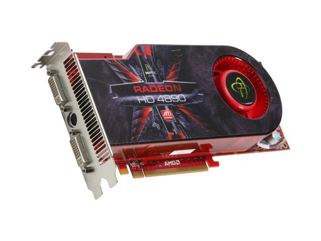
XFX Radeon HD 4890 HD-489A-ZDFC Video Card

---------------------------------------------------------------------------------------------------------

COOLER MASTER Hyper 212 EVO RR-212E-20PK-R2 Continuous Direct Contact 120mm Sleeve CPU Cooler Compatible with latest Intel 2011/1366/1155 and AMD FM1/FM2/AM3+

Spent another $29 on a fan I didn't really need.   I was planning on using the stock fan that comes with the processor, but my CPU is taking too long to come and meanwhile I read too many reviews.  Plus Newegg sent me a promo code.


Finally!  The 4770K processor came.   There was a problem with the order at the Intel Employee store, then it had to come cross country by snail.
Photo


Popped open the socket by unhooking and lifting the clamp wire


I had a little trouble with the fan's backplate.   The case has a handy hole on the back panel so you can access the back of the processor.  Only problem is that two of the holes are misaligned and are hidden beneath the metal.   A little jiggering and holding nuts with needlenose pliers I was able to get the bolts in.


I was a little unhappy when i flipped it back over.  The mounting posts are on top of some of the DDR traces, and during bolting in there were some scrapes on the board where the posts turned.  Hopefully the DDR traces are not disturbed or shorted.   There may be some impedance mismatch with the bolt on top, I'll have to wait and see if I have memory issues.


The X piece fits over the fan heat plate and screws in.  Not too tricky once you figure out how it is supposed to go.
Photo

Snap the fan on the side of the heat sink.  What a monster.
Photo

Wow.   This is one of the most crowded cases I've had.  Not sure why it is so tight, the case itself must be on the small side.


Wired and checked connections, plugged in monitor, keyboard and power.  Pushed the button.  Dead.  Cold.   Dead.  Pushed the button on the board.  Dead.  Fail.

After I unplugged everything I saw the problem.  Stupid stupid stupid.   In this case the power supply is on the bottom.  I like that design, it is in a much better place.  However that means it is upside down and the power switch is upside down.  I had it turned off.    Ha ha ha.

Wired it back up and w00000t!!!!   It boots to the ASROCK screen.  3.5G i7 3770K is reported, with all 16Gb of memory.  Sweet.
CPU temp is 38C.  Set fans to performance mode.

Problem with the DVD drive.  Detected it but wouldn't boot from it.   Strange.  Replaced the SATA cable.  Got stuck again saying to insert boot media.  I"m using a Win7 upgrade DVD which I'm pretty sure I cold booted from on my last build.  But it ain't happening.  I do remember in the past I always bought IDE DVD drives because I've never had good luck booting from SATA.  That is no longer an option, there is no IDE support.

Just for laughs I put in an old Ubuntu live CD.  8.06.  Ancient.  Same result, won't boot, says Select proper boot device.

Tried an old ubuntu boot thumb drive.  Boot error.  Arrggh.

Tried putting in the DVD that came with the mobo.   Can't boot.  Can't read.

http://www.tomshardware.com/forum/250291-32-booting-sata-drive
I guess this is an old problem.  May not be my drive.  This is an old copy of windows and it doesn't like SATA drives for booting.

I hate to do it, but I may try to boot from the old hard disk, just to get going.
Plugged in the menagerie of old SATA drives.  I have one IDE disk that I'm planning to use via an adapter once things get going.

At least now it seems I can boot Windows 8 from my old hard drive.  I still want to drop back to windows 7 and load it on the SSD.  But I need to make this box do something useful.   I have the desktop!
I had to re-register windows over the phone.

Can't seem to get the network running.  Running the mobo DVD to see if I need drivers.
Now I learn I had the mobo DVD in upside down.  Idiot.  Now that windows is up, the DVD drive works fine.  Installed all drivers off the DVD.   Manually had to install LAN drivers to get the internet working.

Can't see the built in Intel graphics at all.  Seems like a driver must be missing.  Two of four monitors aren't coming up.

Windows experience index for the processor is 8.1.  Seems like it should be higher, but I haven't OC'd yet.  4890 gets only a 7.5.   The old disk drives are dragging down to 5.9 and the system seems slow as a pig.  A fairly in shape pig, but not what I wanted.  I need to figure out how to get the OS moved to the new SSD and get the garbage cleaned out.

Looks like I"m bogged down with drivers installing, each one taking half an hour then forcing a reboot.  In the background the backup software is running, etc.

After getting the machine running with Windows 8, I tried again to install windows from my CD onto the SSD from within the OS.   This should have worked.  However the drive spun and never identified the disk. Whaaa?  I opened the drive and looked at the disk.  Big smear on it.  Cleaned it and put it back in.  It works now.   I pulled the old hard drives and tried a fresh boot and now it works!!!!   OK the whole problem with the Sata DVD drive was only that the disk was dirty, and the other disk was in upside down.  Unbelievable. There is no problem booting from a SATA DVD drive for a fresh install. Geeez.

I loaded windows 7 on the SSD successfully and went through all the updates.  I needed to load all the drivers from the mobo CD to get the internet LAN working at all.  That took a zillion reboots and hours, but no major issues.

The built in Intel graphics aren't working.   The device manager doesn't even see them.  A little poking yeilds an unpleasant result.
http://www.intel.com/support/graphics/sb/CS-031040.htm#8
Can I install an external PCI Express* graphics card and use it in parallel with Intel graphics? 
No, Intel graphics cannot be used along with an external PCI Express graphics controller. Installing a PCI Express graphics controller will disable Intel graphics.

Ouch!  I can't do what I wanted and drive two monitors from the mobo and two from a PCIe card.  I'm going to have to install the second 4890 card or my little 5450 PCIe x1 card to get the other two monitors.  Too bad.
I tucked the other Radeon 4890 card into the mobo after all.   Wow this build is insane.  I also put a spare case fan on the case cover because I started to worry about the heat.


A slight issue is that the second Radeon 4890 has a case fan glommed on the side because it's real fan died.   That fan is extending over and blocking one of the USB3 headers.  Until I fix that, two of the USB3 on the front panel won't be operational.

Rebooted and now all four monitors come up.  Hooray!

The SSD windows experience index is only 5.9.   No better than the old drive.  I think I need to try it in another SATA mobo slot and make sure I have a SATA3 cable on it.  
I found a couple tweaker pages that helped

Simply moving the SSD to the Intel SATA port on the mobo improved things from 5.9 to 7.9.  Whew.   Now my poor 4890 graphics card is bringing up the rear.  Strange in windows 8, the processor was an 8.1.  Now it is only 7.8.  But I haven't OC'd it at all yet.

Put the video cards into crossfire, no appreciable difference.  Graphics is the lowest number with two Radeon 4890s in crossfire.


CPU-Z results below


Tuesday, June 4, 2013

Lightning blows hole in wireless router IC

Lightning strike nearby last weekend caused a power surge and destroyed a bunch of stuff at my house and tripped breakers.

One of the victims was my ASUS RT-N16 wireless router.  Overall a fine router, one of the best I've had out of dozens.

I wouldn't have expected the router to be susceptible to this sort of damage.   It runs on a 12V wall wart which I thought would have died first.   However, after the strike, the cable modem no longer thought it had anything connected on the ethernet port, the wireless was off line and none of the devices plugged into the 4 wired ethernet ports saw the network.   Lights on the front were green and quite normally flickering but nobody is home.

Strangely the cable modem in front of it was fine.  The second router plugged in back of it, an old Buffalo DDWRT router that I use as a guest network, was also working fine.  Very weird.

Tried a reset.  Tried connecting a PC through Ethernet and opening the admin page.  Nothing.
I opened it up just for fun and the pictures are worth sharing.

Here is the router


Here is the board inside the router.  Notice anything amiss?


I was expecting to find a bubbly electrolytic cap or a fried diode near the power supply.  Everything there looks OK.

Whoa!   What is this?  This Broadcom IC has a hole blown in the top of it!


Part number reads Broadcom BCM53115SKFBG
http://octopart.com/datasheet/bcm53115skfbg-broadcom-12294970-11798263
This is a 5 port ethernet switch chip.  So no wonder the ethernet lights on the front blink mindlessly and nothing can connect to any of the ethernet ports.  Strange though, I'd have expected the wireless to still be on line.

Guess there is no saving this router.  Open wallet and order another one just like it.
 

Monday, June 3, 2013

Lightning strike killed the LG 55LW5700 TV - Fixed it!!!!!

This post is about repairing a LG flat screen TV.

Last night we heard a really close lightning strike that blew three breakers in our house.  It killed everything that was connected to my wired ethernet network.  It killed the FIOS box, my desktop computer (which was behind a surge protector), my ASUS wireless router, my son's desktop computer - just the ethernet port, the ethernet port on the Sony TV, and worst of all my fairly new LG 55LW5700 TV.

The LG 55L5700-UE TV is dark.  The standby light blinks slowly red about once a second.  Pressing the power button makes the light turn solid red.  No picture, black screen, no sound, no other life.  Pressing again and back to flashing slowly red.

I did buy this at Costco, less than 2 years ago.  I could take it back and play dumb and say that it just doesn't work.  However I know it was killed by lightning which the warranty doesn't cover.   Ethics aside, the kicker is that it is easier for me to fix it by swapping a board then haul it to Costco or ship it anywhere for repair.  It is a friggin 55" TV.

I suspect the power supply board, given the known power surge.
http://www.fixya.com/support/t17617660-red_flashing_light_tv_power_went_out
Some worries that the strike clearly traveled through my ethernet wires as well, my router was blown, and the set is using wired ethernet.   I might be replacing the main board too.

Found a couple boards around the net that say they are for the set, but part numbers vary.  The picture looks consistent.


  • LG 55" 55LV5400-UB 55LV355B-UA 55LV3700-UD EAY62169901 Power Supply Board(BX2)


To open up the set and check the board, I'd have to take it off the stand, unwire it, and remove about a dozen screws while I balance it on edge.   While that is unavoidable, I don't want to take it apart and let it sit there propped up for 3 weeks waiting for the part.  I'm going to pull the trigger and buy a new board without really testing or even opening the set to see which exact power supply I have.   In engineering we call this being a cowboy.   I'm going to make a 40 dollar gamble that this is the problem and that I'm buying the right board.  If it is totally wrong I can resell it on ebay.

Finally bought this one.   I'm taking a risk that it isn't the correct board.  Paid $59 + 12 shipping.  I had bought a cheaper one, but the seller cancelled the transaction saying the board was cracked.
BRAND NEW GENUINE LG POWER SUPPLY BOARD P/N EAY62169901 55LW5600UA EAX62876201/9
http://www.ebay.com/itm/271212434286?ssPageName=STRK:MEWNX:IT&_trksid=p3984.m1497.l2649


Waiting for the new board to come... then I'll post pictures of replacing it.

The board came.


Took the TV off the TV mount and removed the brackets.   Took it down and leaned it against the sofa, so that is was still standing vertically with the screen against something soft.   NEVER lay a set like this down flat on it's face.   The glass can't support the weight and may crack.   Then I removed all the screws around the perimeter of the set.  Must have been 20+ screws.  this is the S/N tag.


The screws are all around the outside edge, and a few around the patch panel on the right.


The only tricky part is that there are a couple screws around the video connections, and the one I missed is in the middle of the RCA video plugs.


Once they were out the back comes right off.


The power supply board is right on top in the middle.


Squeeze the two sides of the power connection and it slides out.


The connectors slide out.  There are two types.  Some you squeeze the two sides and slide it out. A small screw driver can be used as a mini crowbar to separate connectors while you squeeze with the other hand.


  The others have a tab in the center you need to lift to unhook.


Luckily the part number of the power supply board was the same as the one I had bought, EAX62876201


I did notice that the new board is actually an older rev, Rev 1.0 vs the board in my set was Rev 1.1.   They look pretty identical so i'll forge ahead.


I put in the new board and powered up the set.  FAIL.  The set is doing the same thing.  The red light flashes and nothing else works.   You would have thought it was the power supply board zapped, but the surge hit the Ethernet on all the other devices so I should have known it was the main board.

This is the main board on the right.  It has a number of similar connectors requiring squeezing the outer edges and a handful of screws to take out.   The ribbon connectors on the left were the hardest.  Again squeeze the tabs on either side and use a small screwdriver to separate the connector.  Stick the screwdriver in a crack and wiggle and turn it.  A little finesse and they are out.


Here is the part number of the main board.


Found one on Ebay for $73.  Waiting for it to come.  Note that all these LG sets use the same board so it really doesn't have to come from the same type.
http://www.ebay.com/itm/261225522164?ssPageName=STRK:MEWNX:IT&_trksid=p3984.m1497.l2649

The new board came today.   It looked pretty much the same as the old one.  I didn't take the time to compare it exactly, I ran down and popped it into the set.  Attached the board with it's screws and slid in all the connectors.

It was not that exciting or difficult to install.   I plugged in the set before putting the cover back on.  Red light was no longer blinking.  Pulled out the remote, pressed power, and baaadaaaaaabing!   Win!  Set came right on, and the picture was there.  I had to reset up everything because of course, with an all new board it had forgotten all the internet SSID, Netflix passwords, etc.


The hardest part was actually getting the cover back on.   I propped the TV set up against the sofa and worked on it vertically since you never want to lay a big TV flat.   When i put the TV back on, it was tough to line up the screws and keep the front plastic bezel from popping out.   I had a couple extra screws when I was done.   Once I slipped and the set almost fell over.   However all was good.

Since the board was from a 47LW5600 not a 55LW5700 I need to go into the service menu and reset the set type and turn on some of the features, like the audio settings.  I covered that in another post, you need the correct universal remote and the password.   This isn't absolutely necessary, the TV works fine it just thinks it is another model.  Some of the video modes, local contrast options are turned off.
http://blog.workingsi.com/2012/02/hacking-lg-55lw5700-tv.html


My new RCR312WR.  See the Guide button.
Put in the 5 digit code 11265 on this one.  Hold the TV button and type it in.  

Went to the TV and pressed the guide button.   Enter 0413 as the password. 
Press guide and the code box pops up.   Type 0413
Adjusted the TV model and size back to 55" and turned on the picture modes, audio, etc.

Anybody with  Philips head screw driver, some patience and an Ebay account can do this repair and amaze your friends.  Even other electrical engineers were amazed I took this on.  You have to have faith that sets are modular and easy to open and swap boards.  If they weren't they'd cost the manufacturer tons of money. Back in business for <$160.   It might have been half that if I had replaced the main board first.  I could resell the power supply board, but I'd have to put it back in and prove it was good before I could sell it, and I want to get on with life.

Since I did this I did some more googling and there are youtube videos on the process, which i haven't looked at.

Friday, April 5, 2013

Raspberry PI playing

Bought a Raspberry PI board from Adafruit.  This is a small ARM based complete computer for <$40 with a bank of general purpose IO pins, like an Arduino.  It runs LINUX from an SD card.    The point is this is a more powerful prototyping platform than the Arduino.   I'm not totally sure what I'll use it for, it is a toy to start with.
Raspberry Pi Model B 512MB RAM

http://www.adafruit.com/products/998

I decided to go mainstream and get the PI but there is some other interesting stuff out there.


Found some articles on competing products,
http://www.tomshardware.com/news/ODROID-X-Raspberry-Pi-Quad-Core-Buy-Online,16293.html
This one has a GPIO breakout connector
The android OS appeals to me, since I already know how to write Android apps.
http://www.hardkernel.com/renewal_2011/products/prdt_info.php
This one has an add on breakout board for IO, but says the example code "will be released".  The company website is half in Korean.  I'm sure it is great but it could end up being a major headache and hours of non fun debugging software and getting unsupported stuff to work.  No thanks.

This one looks more promising.  It has a GPIO header.  $79
http://www.tomshardware.com/news/VIA-APC-8750-WonderMedia-ARM-Neo-ITX,15721.html

Android 4.0
The previous version was trashed on newegg for being slow, unstable and useless for video
http://www.newegg.com/Product/Product.aspx?Item=N82E16813177001
Web page is minimalist at best.  That is kind of cool, but...
The forum is dead.  Can only buy the new rock board from them.

I also picked up a  breakout connector for the IO pins
Adafruit Pi Cobbler Breakout Kit for Raspberry Pi - Click Image to Close
http://www.adafruit.com/products/914

and a plastic case


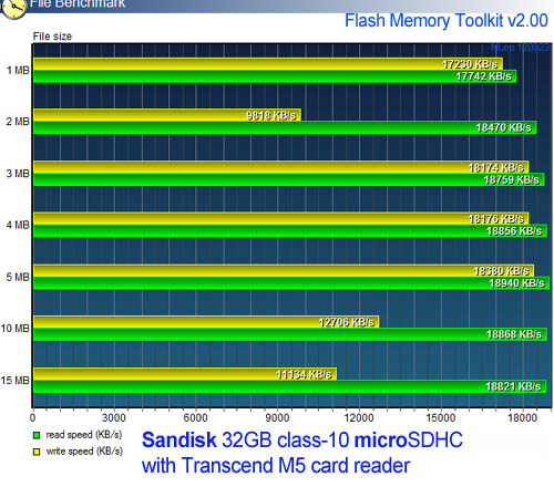
It also needs a >4Gb micro SD card.  I chose a class 10 16G to try to keep the disk write time to a minimum.

It takes some digging to figure out what SD cards are faster.   Retailers don't always show the speed.
I stuck with SanDisk, having worked with them in my real job they are a reputable company and they try to meet the specs they claim.

Sandisk 4GB MicroSDHC Memory Card with SD Adapter (BULK Packaging) - This one turned out to be Class 2 I think, not totally sure but there was a user post with a speed rating


This initially identical $6 card has a part number in the description.   SDSDQ004GA11M
SanDisk 4GB microSDHC Memory Card
That leads me to learning it is Class 4


Finally, This card from Amazon is Class 10 for $15
SanDisk Ultra 16 GB microSDHC Class 10 UHS-1 Memory Card 30MB/s with Adapter SDSDQUA-016G-U46A


So altogether so far I've spent $74 + $6 in shipping
  39 for the R PI
  12 for the case
   8 for the breakout
  15 for the SD card

Not as cheap as you'd think.  I probably have a phone charger, HDMI cable, USB keyboard/mouse I can use.   But if I had to buy all that I'd be over $100.

While I wait for it to come:

Some notes on ideas of what to do with it...
  • Internet connected appliance that moves something depending on web info like stocks, weather, user commands.  
  • Remote activated widget from smartphone
  • Connect to webcam and do some image processing function.  
  • Drive my laser light show, the Arduino wasn't making the rate I needed.
Operating system downloads are here:
http://www.raspberrypi.org/downloads

Looking for some examples of how to use the GPIO to communicate with the real world.
https://projects.drogon.net/raspberry-pi/gpio-examples/
https://projects.drogon.net/raspberry-pi/gpio-examples/tux-crossing/gpio-examples-1-a-single-led/

Downside seems to be that it is 3.3V logic, not 5V, so interface will be different.  Less voltage for some analog interfaces.

Programming appears to be in Python or C.  I haven't used Python, and I'm hesitant to learn yet another coding language.  It appears I can use C and linux command line.   I'm hoping this doesn't turn into being a software exercise that slows down the hardware fun!

Good article on using it as a media center
http://lifehacker.com/5929913/build-a-xbmc-media-center-with-a-35-raspberry-pi

Started by downloading the basic wheezy distro zip file 2013-02-09-wheezy-raspbian.zip
http://www.raspberrypi.org/downloads

"To use an image file, you will need to unzip it and write it to a suitable SD card using the UNIX tool dd. Windows users should use Win32DiskImager. "
http://sourceforge.net/projects/win32diskimager/   downloaded win32diskimager
unzipped the diskimager and the wheezy download zip file.
Ran the diskimager exe and pointed the diskimager at the unzipped .img file and the new 16Gb SD card and hit write.  It took a few minutes and said done.   Now the SD card can't be seen by the PC anymore.  I suppose that is normal but I was hoping that the SD card could be a way to transfer files back and forth.

Got the raspberry PI in the mail.  Plugged in the SD card I formatted above.  Plugged in the USB cable to a phone charger, used an HDMI to DVI adapter cable to plug in a monitor.   Plugged in a USB keyboard and mouse.  Ethernet too. Voila!  It booted right up to the desktop after one setup screen.  I can surf the web.

Here is the screen with the desktop and linux terminal and the browser open, it was able to see the internet with no effort whatsoever.


I'd like a virtual keyboard so I don't need the USB keyboard.
http://www.raspberrypi.org/phpBB3/viewtopic.php?f=50&t=13735
sudo apt-get install matchbox
Then to to the accessories window and keyboard is now there.  A virtual keyboard pops up.  This is good for remote control apps

Tried to play a youtube video, it complains about missing flash

1. apt-get install gnash
2. apt-get install browser-plugin-gnash

You need to type sudo first to get permission
Got lots of errors when it ran 404 errors not found, etc.. Fail
1
sudo apt-get install iceweasel browser-plugin-gnash
still got lots of 404 errors

Did some looking to see if I can run Java on this platform, so I don't have to learn Python.  Seems I can but memory space is very limited
http://www.oracle.com/technetwork/articles/java/raspberrypi-1704896.html

Here is a tutorial on the GPIO
http://log.liminastudio.com/writing/tutorials/tutorial-how-to-use-your-raspberry-pi-like-an-arduino


This example has a different numbering scheme...


I connected an LED and 2.2K resistor between the 3.3V power and GPIO 4 on the header and I wanted to light it up.


Flailed around alot with GPIO examples, not reading carefully, trying to download stuff and failing.
I learned that I needed to do a software update to my Raspberry PI OS because all the app-get commands were failing.  This turned out to be key, even though I just imaged the disk straight from the RPi website yesterday.


sudo apt-get update 
sudo apt-get upgrade

Now the instructions in app-get have started working.

The definitive GPIO work appears to be this page:
https://projects.drogon.net/raspberry-pi/wiringpi/
This is how you install it and build it...

First install git.
sudo apt-get install git-core


Then install the libraries and build

git clone git://git.drogon.net/wiringPi
cd wiringPi ./build


Now the commands gpio -v, and gpio readall are recognized!

Looks like he numbers the pins differently than the previous examples, but at least combines a table showing all the numbering schemes.   The pin I'm using is pin GPIO7.


https://projects.drogon.net/raspberry-pi/wiringpi/the-gpio-utility/
 I'm using his basic command line utility on this page to control the GPIO pins.c

I flailed a bit until I did things in exactly the correct sequence.  And the LED lights up!  W00t!  This was a bit frustrating up to this point, mostly because the steps weren't really spelled out and I didn't do things carefully and the gpio commands don't complain when you type the arguments all wrong.

This is exactly what did the trick  (after WiringPI was installed using the commands above)
gpio export 7 out     <-allows it to work without being the super user
gpio mode 7 out    <-- sets the pin direction
gpio write 7 0   <--note that my led is set to light up when the output is LOW

After some messing around with bash syntax,  I got this bash script working that blinked the LED.  Far more frustrating than it should have been.  Kept getting weird echo command not found errors on commands that weren't in the file, probably due to unpritable characters I pasted out of web posts.  Finally typing it by hand solved the problem.c

Here is the first code that worked to blink the LED.  Hooray!  Paste this into a file, chmod 777, and then type ./<filename>

#!/bin/bash
gpio export 7 out
gpio mode 7 out
gpio write 7 0

while :
do 

sleep 0.3
gpio write 7 1
sleep 0.3
gpio write 7 0

done

Here is the Raspberry PI in the clear box, lots of wires sticking out of it.  In the lower right you can see the red LED is soldered to a small connector and plugged into the GPIO pins so that it is connected between +3.3V and GPIO7 (or 4 depending on who is counting).  The blink script is running and turning it on and off.


Next I want to try the C complilation method of controlling the rpi GPIO for some more complex apps

I attempted to run the blink program in WiringPI in c code next.  This is how I did it:

  • cd to wiringPI/examples and copied blink.c up to the user's home directory and renamed it cblink.c     


  • I modified LED to output on pin 7, like my bash script.
  • Then I compiled it

cc -o cblink cblink.c -L/usr/local/lib -lwiringPi

  • From the users home directory where the cblink.c program is sitting I ran it.

sudo  ./cblink

And hooray the LED starts blinking, just like my bash script earlier!!!  Win!


  • I want to set up to rlogin into the Raspberry PI so it can be a remote internet appliance
  • Need to set up rlogin
  • Look into wifi communication, finding it on the net, sending messages, etc
  • controlling remotely from a PC or smartphone is probably the ticket.  Then I'd like to build an Android app that talks to it
http://jerbly.uk.to/picam
THis guy has done some of the homework to remote control the PI

This page has info on remote login to the pi
http://simonthepiman.com/how_to_setup_remote_access.php
I don't really want to go with a fixed IP address as he describes.  I'd much rather set up a system where the remote control and the raspberry pi find each other on the network.

It looks like putting .rc files in /boot will run them at starup.  Im not sure about this yet but I need to know how to execute code on boot for when the rpi is running as an embedded machine.  Need to come back to figure this out

A couple posts on remote login from this page
http://www.raspberrypi.org/phpBB3/viewtopic.php?f=2&t=742&p=17694

by obarthelemy » Wed Sep 14, 2011 1:31 pm
From my perspective (newbie, with a Windows main PC), there's 4 ways to do it, from simplest to install and barest functionality/comfort, to hardest to install but peachy once you've got it to run:

- get a text command line, via SSH and Putty on Windows

- do a kind-of Remote Desktop (Windows style) via a VNC server on the Pi, and a client on Windows. There's Ultra-, Tight-, True-, and plenty other VNCs for that, all with versions for windows, Linux (lots of flavours), and plenty other OSes, it is very standard. Be aware though that VNC does bitmaps, not vectors, so a lot more data needs to travel between the sever and client. Redraws are slowish and ugly.

- do a true Remote Desktop from Windows, using Windows RDP protocol, thanks to FreeNX server on the Linux machine. Vectorial, hence much faster and pleasant.

- take advantage of X11, which natively supports displaying one PC's stuff on another. Most Linuxes' user intefaces (lxde, gnome, KDE...) use X11. But Windows doesn't really have it, and getting it to run is a pain, the best solution I could find was actually install a Virtual Machine running Linux on my Windows PC, and do X11 remoting from there. Otherwise, there's a whole lot of hooplah involving Cygwin that's good for giving headaches, mainly.

Actually, a package and doc to enable good remoting to the Pi would be a very useful projects for those of us who do have a Windows PC.
Posts: 1399
Joined: Tue Aug 09, 2011 10:53 pm
by mahin » Wed Sep 14, 2011 2:18 pm

What you are looking for is FreeNX [ lacking development will not work out of the box ] NoMachine [ Commercial nothing ready for R-Pi ] and x2go. X2GO is Free / Open Source and being actively developed. It is now used with Skolelinux doing just what you are seeking. Seeing the specs of R-Pi model 'A' it is suitable. With Debian working on R-Pi x2go will also work but not yet tested.

You need not learn any thing to use that x2go on R-Pi a simple log-in will do, unless you wish to contribute then do learn about Linux.


I need to find out what the IP address is so I can attempt remote access
basically it says ipconfig!  I tried that first, I'm no noob, but it doesn't work!  I get sudo: ipconfig: command not found.  Whaaa?

Tried going to my router page and looking at the devices.  My home network has 33 devices on it!   Family of 5 with laptops, TVs, game systems, tablets, phones, printers.  Find this one
raspberrypi192.168.2.135

basically it says ipconfig!  I tried that first, I'm no noob, but it doesn't work!  I get sudo: ipconfig: command not found.  Whaaa?

Read more carefully.  if is "ifconfig" not "ipconfig"

ifconfig reports  the IP address is 192.168.2.135
MAC address is b8:27:eb:04:f0:fc


This page describes how to scan for the rpi on the network using ipscanner and puTTY.

Downloaded and installed PuTTY.  Clicked on putty.exe on this page:

Put the IP address above into putty and badaboom!  

I get a login window that asks for user and password. I try "pi" and "raspberry" and I'm in!


I execute my bash script blinkblink remotely and the light starts flashing. I have a achieved remote control access! I'll need a better program on the windows side to find the raspberry pi by MAC address, but a small victory.

Bought a WiFi module to plug into the PI USB from Adafruit. Page says it works right out of the box.


I plugged it in. I had to use the virtual keyboard because there are only two USB. I could have dug up a hub but I was lazy. I hotplugged it and that triggered a reboot.

I disconnected the ethernet cable and clicked on WiFi Config on the desktop. I didn't record the exact sequence of events, but I scanned for my network, found it. Then I double clicked on it (which wasn't the obvious thing to do) and a box came up and I was able to type the password. I'm using WPA PSK and that was fine. It connected and displayed the IP address directly.


Using puTTY from my PC, I could again log into that IP address as user pi, password raspberry and I'm in. Cool. WiFi was a snap.


I want the rpi to communicate over the internet to either other machines or to an android app.  
This post has it sending email.  That is nice, not exactly what I want though.
http://iqjar.com/jar/sending-emails-from-the-raspberry-pi/

This post has it pulling down messages from web sites.  Although there is no explanation of how it works.
http://lukeberndt.com/2013/c-node-js-module-for-spi-bus-led-signs/

Here is a good idea.  Use google docs as a drop box.  The pi will create and read docs.
http://learn.adafruit.com/dht-humidity-sensing-on-raspberry-pi-with-gdocs-logging/connecting-to-google-docs
another one
http://www.danielhansen.org/2013/03/raspberry-pi-temperature-logging-using.html
THese all use gspread to upload.  no mention of download yet.

Setting up a webcam
http://stevenhickson.blogspot.com/2013/03/using-webcam-with-raspberry-pi.html
sudo apt-get install libcv-dev libopencv-dev libcv2.3 opencv-doc
sudo apt-get install python-opencv
http://stevenhickson-code.googlecode.com/svn/trunk/AUI/Imaging/test
chmod +x test
sudo apt-get install scrot


----------------------------------------------------------------------------------------------------------------
This post (like a lot of mine) is just my notes as I learn, and will build as I work on this.  Or it may sit and rot while I'm distracted by another project or life in general :)