Why do this? Monitor live engine, MPG, etc. Diagnose check engine lights, log data on the car.
I'm also thinking the car modders would love to have lights that respond to what the vehicle is doing, flames that brighten when the engine revs etc.
I ordered an OBD II interface cable from Amazon. No way around this one for $10.95+ship
OBDII Cable, J1962M to Open End, 10ft (144505)
There are some adapter cables to RS232, but why add money buying different connectors. I suppose I could have scrounged a 9 pin from an old motherboard. Too much work. Here is the pinout. This cable has an open wire end i can just solder in.

You can also use a OBDII to DB9 cable, seems like the pinout is standard
http://www.elec-intro.com/obd-connector

Sparkfun has this cable
http://www.sparkfun.com/commerce/product_info.php?products_id=10087
You can also use a OBDII to DB9 cable, seems like the pinout is standard
http://www.elec-intro.com/obd-connector
Sparkfun has this cable
http://www.sparkfun.com/commerce/product_info.php?products_id=10087
OBDII to DB9 Cable
sku: CBL-10087
Here is the basic pinout (OBDII > DB9 Female)
| Pin Description | OBDII | DB9 |
| J1850 BUS+ | 2 | 7 |
| Chassis Ground | 4 | 2 |
| Signal Ground | 5 | 1 |
| CAN High J-2284 | 6 | 3 |
| ISO 9141-2 K Line | 7 | 4 |
| J1850 BUS- | 10 | 6 |
| CAN Low J-2284 | 14 | 5 |
| ISO 9141-2 L Line | 15 | 8 |
| Battery Power | 16 | 9 |
SAE J1962 defines the pinout of the connector as:
- Manufacturer discretion. GM: J2411 GMLAN/SWC/Single-Wire CAN.
- Bus positive Line of SAE-J1850 PWM and SAE-1850 VPW
- Ford DCL(+) Argentina, Brazil (pre OBD-II) 1997-2000, Usa, Europe, etc. Chrysler CCD Bus(+)
- Chassis ground
- Signal ground
- CAN high (ISO 15765-4 and SAE-J2284)
- K line of ISO 9141-2 and ISO 14230-4
- -
- -
- Bus negative Line of SAE-J1850 PWM only (not SAE-1850 VPW)
- Ford DCL(-) Argentina, Brazil (pre OBD-II) 1997-2000, Usa, Europe, etc. Chrysler CCD Bus(-)
- -
- -
- CAN low (ISO 15765-4 and SAE-J2284)
- L line of ISO 9141-2 and ISO 14230-4
- Battery voltage
On 1996 and later vehicles, you can tell which protocol is used by examining the OBD II connector:
J1850 VPW--The connector should have metallic contacts in pins 2, 4, 5, and 16, but not 10.
ISO 9141-2--The connector should have metallic contacts in pins 4, 5, 7, 15, and 16.
J1850 PWM--The connector should have metallic contacts in pins 2, 4, 5, 10, and 16.
ISO 9141-2--The connector should have metallic contacts in pins 4, 5, 7, 15, and 16.
J1850 PWM--The connector should have metallic contacts in pins 2, 4, 5, 10, and 16.
The project involves interfacing the car's computer, which runs at 12V. Arduino runs at 5V. After that, it is all software.
The OBD II has a line called ISO K line, which is a bidirectional serial bus.
It seems there are a couple routes people have gone.
- Using an ELM 323 or 327 OBD to RS232 adapter IC. These are $14 on scantool.net, in clearance. Otherwise they are $30 and seem to be hard to buy right now.
- Connecting direct to OBD protocol, using a level shifter.
- Using a MC33290 or MCZ33290EF level translator IC. Found these are hard to get, end of life'd. There may be replacements, but this is not worth the effort.
- Just use some transistors to build one! I have some 2N3904 that cost 33 cents lying around. This guy did it this way. I think this circuit is missing a resistor for the 12 to 5V division, and the first stage should be to 5V to keep the Arduino safe. But it shows the concept. Easy. Cheap. You can see where this is going. Don't be scared of a couple of transistors!
http://prj.perquin.com/obdii/obdii_avr.gif

OK, the ratios of his resistors THEORETICALLY keep the Arduino from seeing 12V, but being a consumer device circuit designer this circuit is not safe. If the K line ever touches 12V, or if one side or the other of this circuit is not powered, RXD will float to 12V and cook the Arduino.
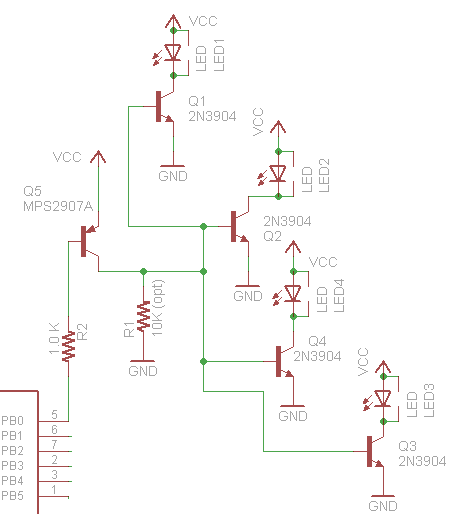
Here is my circuit to replace the MC33290 with a few cheap discrete transistors

NOTE/UPDATE - RX comes from the collector not the grounded emitter on Q4. Schematic is wrong but I no longer have the orginal to edit. This is the way it should be. Somebody pointed this out years ago but for some reason I couldn't see the obvious.

Wikipedia is always my friend. OBDII is a bit more complicated. Different cars use different protocols. Dang. I have Hondas, a 1997 and a 2007. So I'm guessing i can still use the K-line.
This seems pretty straight forward. And i think others have already written the code for the Arduino to emulate this
- ISO 9141-2. This protocol has an asynchronous serial data rate of 10.4 kBaud. It is somewhat similar to RS-232, but that the signal levels are different, and that communications happens on a single, bidirectional line without extra handshake signals. ISO 9141-2 is primarily used in Chrysler, European, and Asian vehicles.
- pin 7: K-line
- pin 15: L-line (optional)
- UART signaling (though not RS-232 voltage levels)
- K-line idles high
- High voltage is Vbatt
- Message length is restricted to 12 bytes, including CRC
This guy has some good info on the codes, but I think his circuits have issues and may send 12V back to the Arduino under certain cases. Ouch. I'll fix that. http://prj.perquin.com/obdii/
Still looking at protocols. Found a nice document at
http://www.esatinc.ca/News_Letters/OBD_II_Specifications_and_Connections.pdf
It looks like CAN bus will be required on all new vehicles by 2008. I probably have a K wire interface on my older car, but it would be nice to build something that has more generic usage. Also diagnostics may only be on CAN in some vehicles. From this doc
It looks like CAN bus will be required on all new vehicles by 2008. I probably have a K wire interface on my older car, but it would be nice to build something that has more generic usage. Also diagnostics may only be on CAN in some vehicles. From this doc
A simple check to see if the CAN bus is in use in a vehicle, and accessible via the OBD socket, is to connect a resistance meter across pin 6 and pin 14. Due to the combined resistance of the two termination resistors at 120 Ohms each the overall resistance should be read as 60 Ohms. (refer to vehicle specifications)
The CAN bus speed may be as fast as 1 MHz, although the OBD-II ISO 15765 specification specifies two speeds which may be used for on-board diagnostics, 250 KHz and 500 KHz.
So it looks like I should support K wire and CAN both.
Cool - a high paydirt google hit give me this. All the electrical stuff is here!
http://www.interfacebus.com/Design_Connector_CAN.html


Most of the CAN IC's have a uController built in, and cost $20+. Yuck. I could handwire a circuit.
Found these parts that might help. for <$5
http://search.digikey.com/scripts/DkSearch/dksus.dll?Cat=2556697&k=MCP2510
This part is probably worth the $5. The CAN bus was going to max out the Arduino and make it hard for it to do anything else. I would have spent $5 on the devices to interface.
http://ww1.microchip.com/downloads/en/DeviceDoc/21291F.pdf
Uh oh! Looks like I need another part to actually interface to the bus. Boo!
http://archive.electronicdesign.com/files/29/4057/figure_01.gif
http://electronicdesign.com/article/communications/build-a-simple-and-inexpensive-controller-area-net.aspx
This guy has already done it, wants to sell for 30GBP. Yikes. I'm thinking a $10 shield will make a nice project.
http://www.skpang.co.uk/catalog/product_info.php?cPath=140_142&products_id=706
Not so bad, the CAN interface chip is only $1.12!
http://search.digikey.com/scripts/DkSearch/dksus.dll?Detail&name=MCP2551-I/P-ND
And there is a cheaper version of the controller: MCP2515-I/P-ND for $1.98! This might be a <$10 board yet!
OK, ordered the MCP2515 and MCP2551 and got them almost immediatly from Digikey. I put together a quick lash up. Then I finally got around to taking the OBDII cable out to the car and checking if I have a CAN bus. I have a 2007 Accord, and some older cars. I was sure the 2007 would have a CAN bus, since they are required in 2008. But you can guess. Nope, open circuit between 6 and 14. Doh! Major setback and I"m going to go back and build the K line version first now.
A thread with info on another person's project
http://ecomodder.com/forum/showthread.php/obd-mpguino-gauge-2702-27.html
So I have my interface circuit together, using 4 transistors, some resistors, diode and a cap. Made a version for less than $5, not including the prototype board. I will write it up once I'm sure it's really working. Need to get some basic code going to begin talking.
Looks like the obduino32K has some good code. These guys have gone way over the top on the code.
http://opengauge.googlecode.com/svn/trunk/obduino32K/obduino32K.pde
Decided to put my OBDII K line interface circuit together with an LCD and load the obduino32K code.
The code compiled without much trouble, and the LCD comes on, and the K line gets wiggled. Today I will plug it into my car and see what happens. See the circuit diagram above. Basically I am building the circuit from http://code.google.com/p/opengauge/wiki/OBDuinoDiagram but I am not using the MC33290, since I couldn't find one. I put together a level translator with a handful of cheap transistors, similar to the diagrams I quoted above. Functionally equivalent to this picture: Also odd that there are no pull up resistors on the switches.

OK - debug time. The board comes up, the K line wiggles. I tried this in two Honda's and a Toyota and never get past the initial sync. I need to strip down this code to a basic sync and a dump of the response to see if the car is responding and I'm missing or mangling it, or if there is no response. I looked at the data sheet of the MC33290 and I'm pretty sure my circuit should work. I have an LED on the K line (not directly) so I can see there is activity.
Still stuck. I can't get the car to respond to the Init. May be i'm using the wrong protocol, my interface circuit may have problems, or my code is no good. I'm going to begin to deconstruct things and start with some basic bit banging the control lines to see what is up.
I posted my tweaked openguage code so i can pick it up from my laptop, and try debugging in the car...
http://www.interfacebus.com/Design_Connector_CAN.html
Most of the CAN IC's have a uController built in, and cost $20+. Yuck. I could handwire a circuit.
Found these parts that might help. for <$5
http://search.digikey.com/scripts/DkSearch/dksus.dll?Cat=2556697&k=MCP2510
This part is probably worth the $5. The CAN bus was going to max out the Arduino and make it hard for it to do anything else. I would have spent $5 on the devices to interface.
http://ww1.microchip.com/downloads/en/DeviceDoc/21291F.pdf
Uh oh! Looks like I need another part to actually interface to the bus. Boo!
http://archive.electronicdesign.com/files/29/4057/figure_01.gif
http://electronicdesign.com/article/communications/build-a-simple-and-inexpensive-controller-area-net.aspx
This guy has already done it, wants to sell for 30GBP. Yikes. I'm thinking a $10 shield will make a nice project.
http://www.skpang.co.uk/catalog/product_info.php?cPath=140_142&products_id=706
Not so bad, the CAN interface chip is only $1.12!
http://search.digikey.com/scripts/DkSearch/dksus.dll?Detail&name=MCP2551-I/P-ND
And there is a cheaper version of the controller: MCP2515-I/P-ND for $1.98! This might be a <$10 board yet!
OK, ordered the MCP2515 and MCP2551 and got them almost immediatly from Digikey. I put together a quick lash up. Then I finally got around to taking the OBDII cable out to the car and checking if I have a CAN bus. I have a 2007 Accord, and some older cars. I was sure the 2007 would have a CAN bus, since they are required in 2008. But you can guess. Nope, open circuit between 6 and 14. Doh! Major setback and I"m going to go back and build the K line version first now.
A thread with info on another person's project
http://ecomodder.com/forum/showthread.php/obd-mpguino-gauge-2702-27.html
So I have my interface circuit together, using 4 transistors, some resistors, diode and a cap. Made a version for less than $5, not including the prototype board. I will write it up once I'm sure it's really working. Need to get some basic code going to begin talking.
Looks like the obduino32K has some good code. These guys have gone way over the top on the code.
http://opengauge.googlecode.com/svn/trunk/obduino32K/obduino32K.pde
Decided to put my OBDII K line interface circuit together with an LCD and load the obduino32K code.
The code compiled without much trouble, and the LCD comes on, and the K line gets wiggled. Today I will plug it into my car and see what happens. See the circuit diagram above. Basically I am building the circuit from http://code.google.com/p/opengauge/wiki/OBDuinoDiagram but I am not using the MC33290, since I couldn't find one. I put together a level translator with a handful of cheap transistors, similar to the diagrams I quoted above. Functionally equivalent to this picture: Also odd that there are no pull up resistors on the switches.
OK - debug time. The board comes up, the K line wiggles. I tried this in two Honda's and a Toyota and never get past the initial sync. I need to strip down this code to a basic sync and a dump of the response to see if the car is responding and I'm missing or mangling it, or if there is no response. I looked at the data sheet of the MC33290 and I'm pretty sure my circuit should work. I have an LED on the K line (not directly) so I can see there is activity.
Still stuck. I can't get the car to respond to the Init. May be i'm using the wrong protocol, my interface circuit may have problems, or my code is no good. I'm going to begin to deconstruct things and start with some basic bit banging the control lines to see what is up.
I posted my tweaked openguage code so i can pick it up from my laptop, and try debugging in the car...